
System and Method of Controlling Fuel Delivery During Positive Valve Overlap Operation of an Engine Start

a technology of positive valve overlap and fuel delivery, which is applied in the direction of electric control, machines/engines, output power, etc., can solve the problems of air-fuel combustion errors in the cylinder, and achieve the effects of increasing engine output, increasing internal residuals, and increasing fuel economy

Active Publication Date: 2007-12-13
FORD GLOBAL TECH LLC
View PDF8 Cites 10 Cited by
  • Summary
  • Abstract
  • Description
  • Claims
  • Application Information

AI Technical Summary

Benefits of technology

[0001]Engines may use variable cam timing to vary intake and / or exhaust valve timing to provide various engine operating effects, such as increased fuel economy, increased engine output, increased internal residuals, and more.
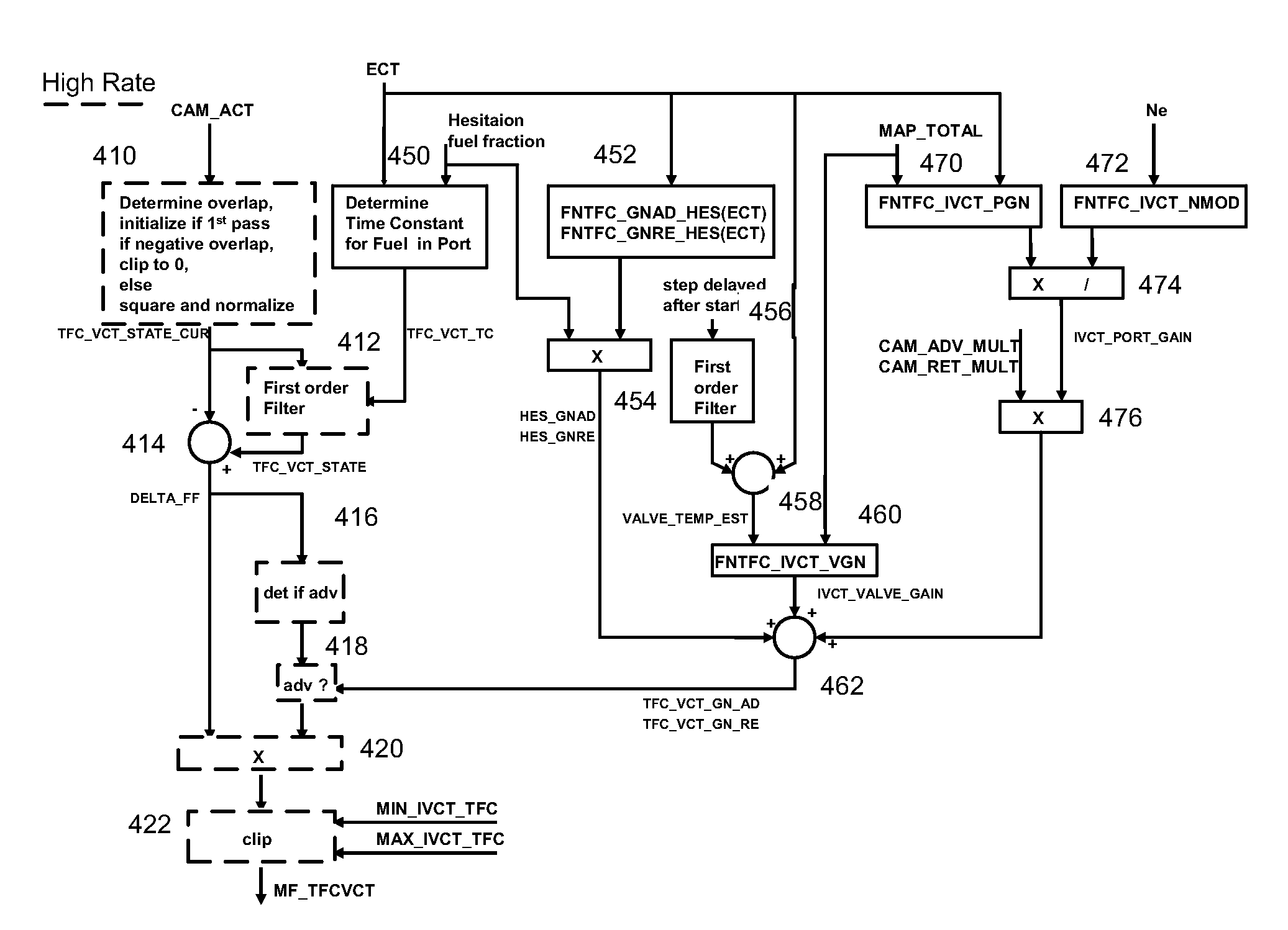
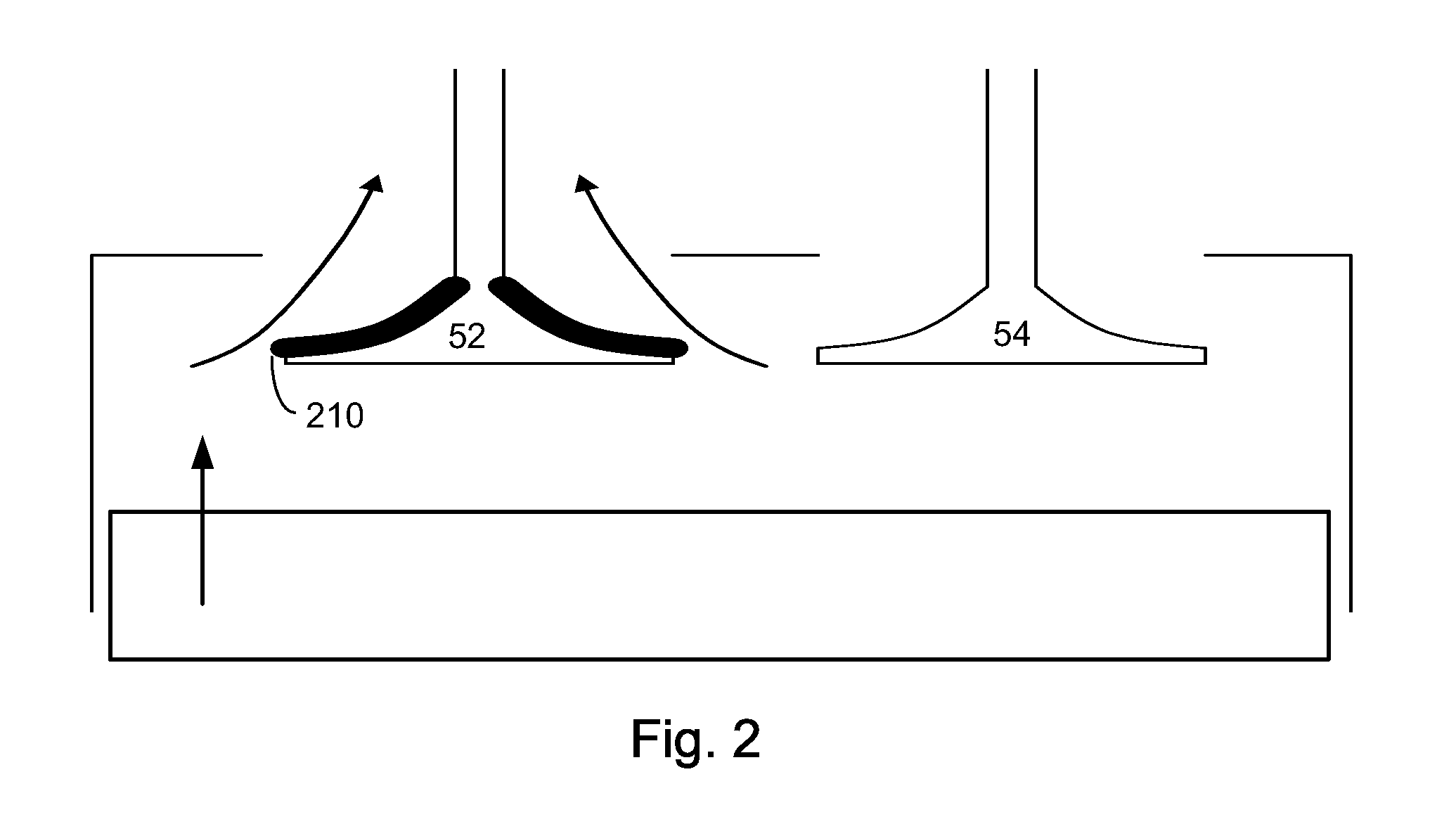
[0005]In this way, it is possible to enable a engine to be operated with changes in intake cam timing to allow residual gas from the cylinder to flow back through the intake port at the end of the exhaust stroke (in which the intake valve is starting to open and the exhaust valve is still closing) during engine starting conditions. As such, the above operation may be used as an intended form of exhaust gas recirculation that exploits positive valve overlap to improve pumping losses, reduce NOx formation, and increase fuel evaporation and mixing.

Problems solved by technology

If positive valve overlap is used during engine cold starting, especially before intake manifolds and / or intake valves have sufficiently warmed, the residual backflow strips fuel from the port surfaces and back of the intake valves, thereby generating air-fuel combustion errors in the cylinder, even though neither the cylinder air amount nor the intake manifold pressure necessarily correlate with the intake cam timing.

Method used


Image

  • System and Method of Controlling Fuel Delivery During Positive Valve Overlap Operation of an Engine Start
  • System and Method of Controlling Fuel Delivery During Positive Valve Overlap Operation of an Engine Start
  • System and Method of Controlling Fuel Delivery During Positive Valve Overlap Operation of an Engine Start

Examples


Embodiment Construction

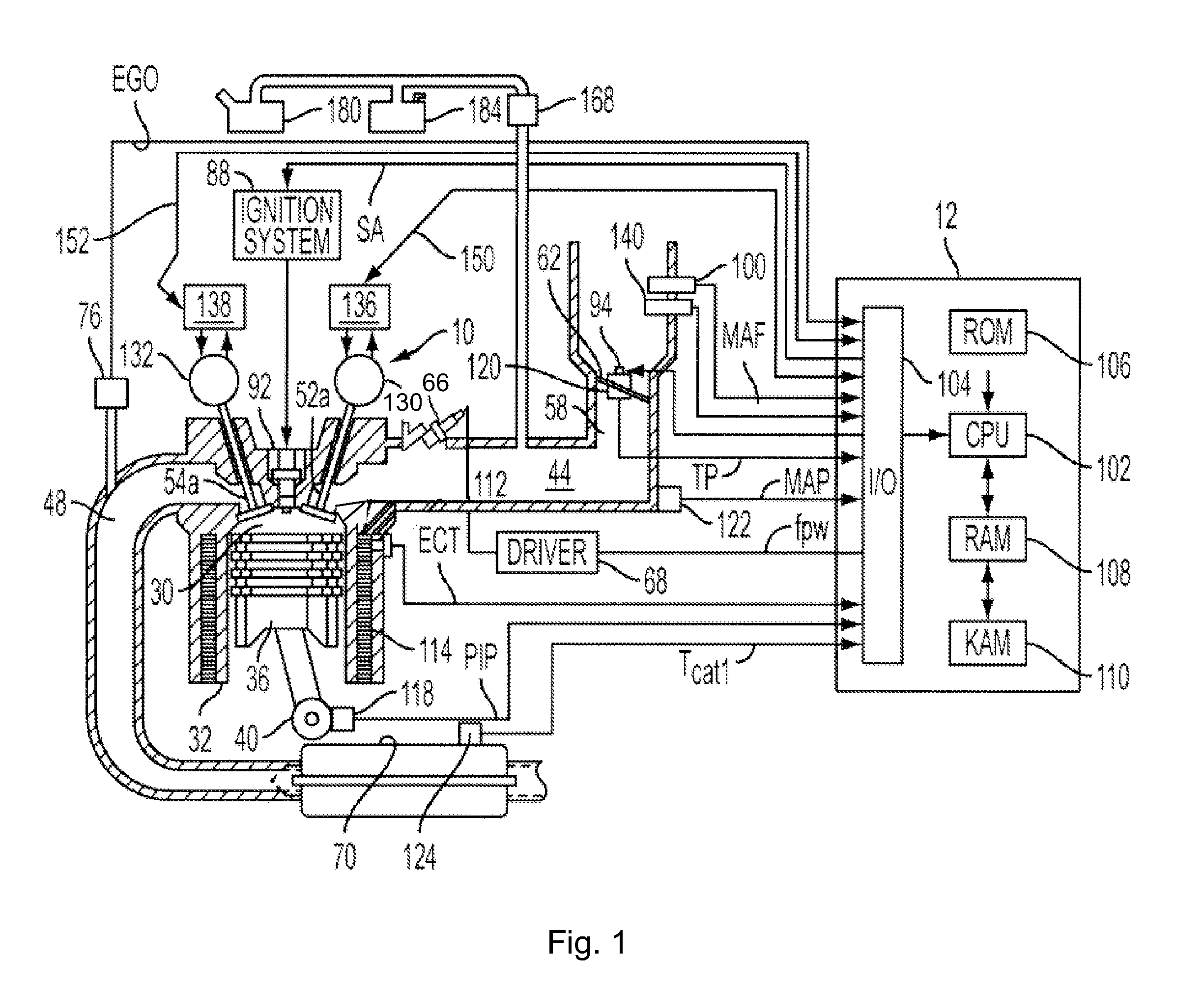
[0011]FIG. 1 shows one cylinder of a multi-cylinder engine, as well as the intake and exhaust path connected to that cylinder. Continuing with FIG. 1, port injection internal combustion engine 10, comprising a plurality of combustion chambers, is controlled by electronic engine controller 12. Combustion chamber 30 of engine 10 is shown including combustion chamber walls 32 with piston 36 positioned therein and connected to crankshaft 40. A starter motor (not shown) may also be coupled to crankshaft 40 via a flywheel, planetary gearset, accessory drive belt, or other linkage (not shown). Combustion chamber, or cylinder, 30 is shown communicating with intake manifold 44 and exhaust manifold 48 via respective intake valves 52a and 52b (not shown), and exhaust valves 54a and 54b (not shown). While in this example two intake and two exhaust valves are used, alternative valve configurations may also be used, such as, for example, one intake and one exhaust valve, or two intake and one exh...


PUM


Abstract

An approach is provided for compensating engine fueling during starting conditions in which positive valve overlap is enabled early in the start. In one example, the valve timing is adjusted to increase positive overlap during cold starting conditions, and fuel adjustments are provided to compensate for the evaporation effects of the increased residual push-back.

Description

BACKGROUND AND SUMMARY[0001]Engines may use variable cam timing to vary intake and / or exhaust valve timing to provide various engine operating effects, such as increased fuel economy, increased engine output, increased internal residuals, and more.[0002]Since the above adjustments can affect air-fuel ratio of the combustion cylinders, various approaches may be used to provide fueling adjustments. For example, U.S. Pat. No. 6,729,304 uses the change of cam phase timing between samples to modify the output of the fuel control system. In particular, in this fuel injection control system, when the valve overlap period is changed due to a change in the cam phase, the fuel injection amount is set according to the detected operating conditions of the engine, and then the fuel injection amount thus set is corrected according to the amount of change in the valve overlap period and the wall surface temperature of the intake ports. In this case, the amount of change in the valve overlap period...

Claims


Application Information

Patent Timeline
Patent Type & Authority Applications(United States)
IPC IPC(8): F02M51/00F01L1/34F02B75/02
CPCF01L1/34Y02T10/18F01L2800/01F01L2800/10F02D13/0203F02D13/0261F02D41/0002F02D41/047F02D41/064F02D2013/0292F02M25/0715F02M25/0752F02M25/089Y02T10/42F01L2001/0537F02M26/01F02M26/13Y02T10/12Y02T10/40
Inventor MAGNER, STEVEZHANG, XIAOYINGROLLINGER, JOHNJANKOVIC, MRDJANWAGERS, SUE
Owner FORD GLOBAL TECH LLC
Learn More