Cooling Apparatus of Looped Heat Pipe Structure

a cooling apparatus and looped heat pipe technology, applied in lighting and heating apparatus, cooling/ventilation/heating modification, indirect heat exchangers, etc., can solve the problems of reduced cooling capability, reduced reliability of semiconductor devices, and limitations of improved conventional cooling methods, so as to improve cooling functions.

Inactive Publication Date: 2007-12-13
THERMALFORCE
View PDF2 Cites 23 Cited by
  • Summary
  • Abstract
  • Description
  • Claims
  • Application Information

AI Technical Summary

Benefits of technology

[0011] It is, therefore, an object of the present invention to provide a cooling apparatus with a looped heat pipe structure which improves a cooling function by preventing a generation of bubbles inside a wick of an evaporator or an inverse flow of a vaporized gaseous coolant through the wick.

Problems solved by technology

This increasing heat emission causes degradation of reliability of a system utilizing semiconductor devices.
Thus, if heat is not sufficiently absorbed from the external heat emitter when a cooling apparatus first operates, there may be a disadvantage that cooling capability is diminished because of the insufficient operation power for circulating the coolant.
Another cooling method of improving the aforementioned disadvantage is the use of a capillary pumped loop (CPL) type cooling apparatus.
However, this improved conventional cooling method still has limitations.
The inverse flow may cause a decrease in the thermal transfer efficiency of the cooling apparatus and increase the manufacturing costs.
The synthetic resin-based substance has a low ignition point and a high degree of thermal transformation and thus, the latter mentioned conventional cooling method may not be used when a brazing process is performed for fabricating an evaporator.

Method used


Image

  • Cooling Apparatus of Looped Heat Pipe Structure
  • Cooling Apparatus of Looped Heat Pipe Structure
  • Cooling Apparatus of Looped Heat Pipe Structure

Examples


Embodiment Construction

[0055] Hereinafter, a cooling apparatus of a looped heat pipe structure in accordance with certain embodiments of the present invention will be described in detail with reference to the accompanying drawings. Also, it should be noted that the same reference numerals are used for the same configuration elements even in different drawings.

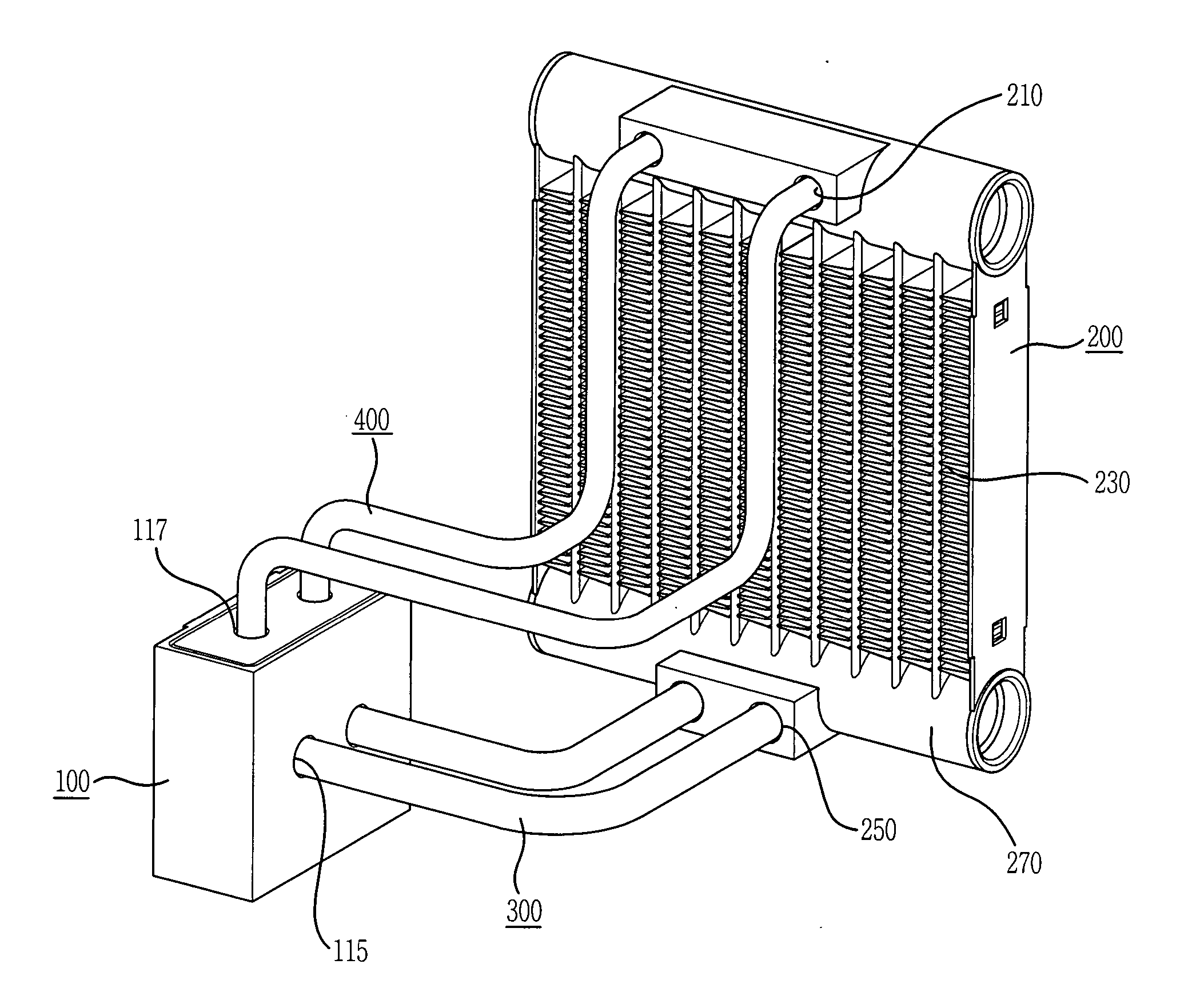
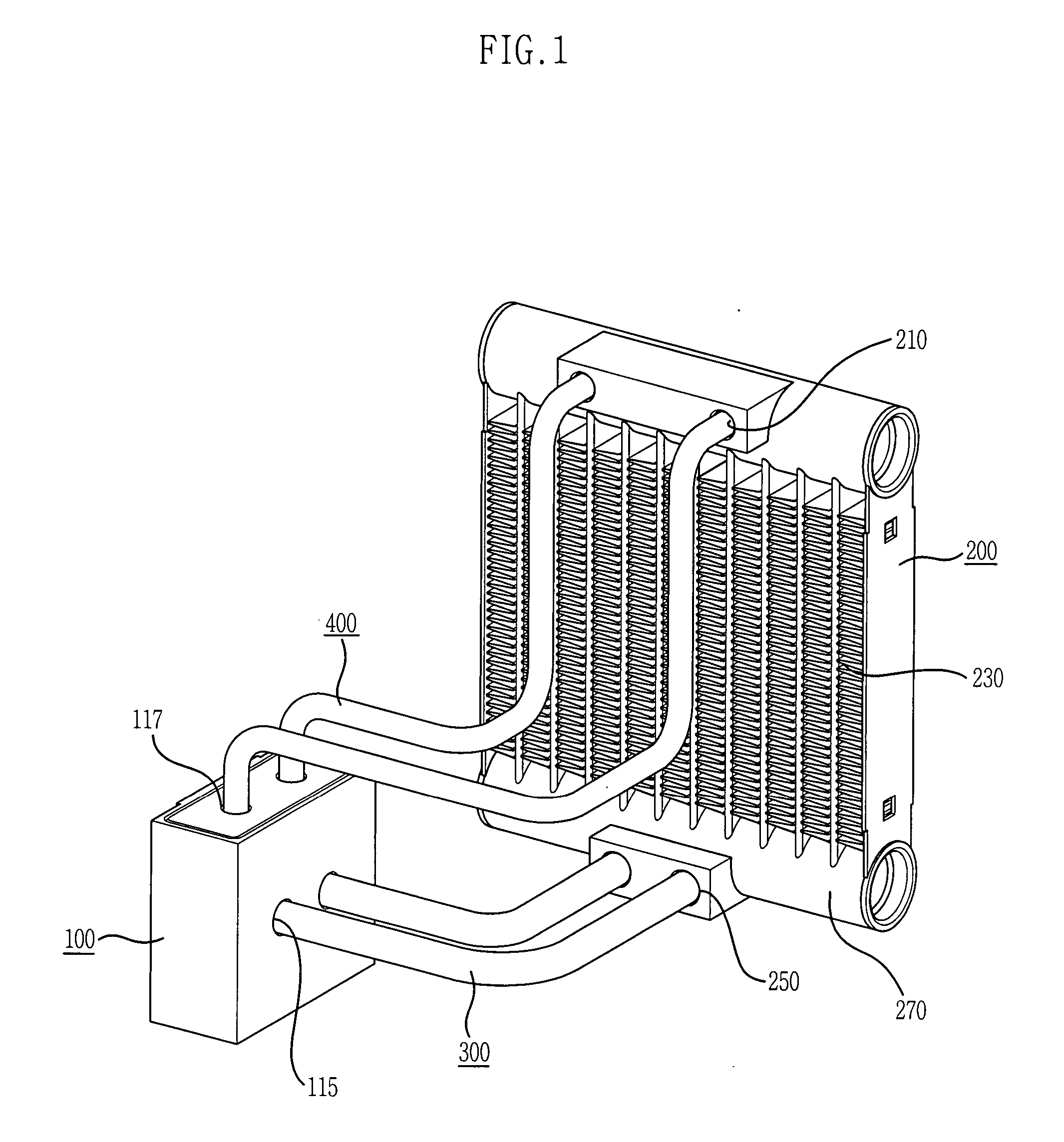
[0056]FIG. 1 is a perspective view showing a cooling apparatus with a looped heat pipe structure in accordance with a specific embodiment of the present invention.

[0057] As shown, the cooling apparatus includes: an evaporator 100 disposed closely to a heat emitter which is a high temperature unit; a condenser 200 disposed at a low temperature unit side; at least one gaseous coolant pipe 400 connecting at least one gaseous coolant outlet 117 of the evaporator 100 with at least one inlet 210 of the condenser 200; at least one liquid coolant pipe 300 connecting at least one outlet 250 of the condenser 200 with at least one liquid coolant inlet 115 of ...


PUM


Abstract

A coolant phase changeable cooling apparatus using a capillary action is provided. The cooling apparatus prevents a generation of bubbles inside a wick of an evaporator or an inverse flow of a vaporized gaseous coolant through a wick. Also, a thermal contact area can be widened by using at least one groove of a gaseous coolant flow passage unit. Based on these provided effects, cooling efficiency of the cooling apparatus can be improved.

Description

TECHNICAL FIELD [0001] The present invention relates to a coolant phase changeable cooling apparatus using a capillary action, and more particularly, to a cooling apparatus which widens heat contact areas of a porous member, into which a liquid coolant is filled by adhesiveness of an internal capillary tube of an evaporator, and the filled liquid coolant and includes a groove which gives fluidity of a vaporized coolant. BACKGROUND ART [0002] As the integration scale of semiconductor devices has been increased, a higher level of heat has been given off per unit area of a semiconductor chip. This increasing heat emission causes degradation of reliability of a system utilizing semiconductor devices. [0003] Hence, cooling technology has been developed to solve the above disadvantage related to the increasing heat emission. One typical cooling method is to use latent heat of a coolant and is advantageous in respect of cooling efficiency, manufacturing costs and installation spaces. That ...

Claims


Application Information

Patent Timeline
Patent Type & Authority Applications(United States)
IPC IPC(8): F28D15/00
CPCF28D15/046F28F21/04F28F21/02H05K7/20
Inventor CHUN, KYO-SEOK
Owner THERMALFORCE
Why Eureka
Try Eureka