Method for Enabling Transmission of Substantially Equal Amounts of Energy

Active Publication Date: 2007-12-13
SIGNTRONIC AG
View PDF0 Cites 25 Cited by
  • Summary
  • Abstract
  • Description
  • Claims
  • Application Information

AI Technical Summary

Benefits of technology

[0010] According to the present invention, disadvantages of using light sources with varying intensity, e.g., short arc lamps with peaking power supply, may be overcome, and in a preferred embodiment even in such a way that the peak intensities are utilized for optimum efficiency.
[0043] According to the present invention, illumination arrangements may be enabled to transmit substantially equal amounts of energy to light sensitive points, thereby overcoming disadvantages of intensity varying light sources.

Problems solved by technology

Unfortunately, their construction, however, also causes displacement of material from the electrodes, causing their voltage ratings to change during use, their lifetime to be reduced, and the point of emission, i.e., the arc, to fluctuate.
Often such solutions introduce new problems and in the example of short arc lamps, the current peaking causes the emitted luminous intensity to fluctuate.
Such fluctuations may, however, not be acceptable for specific uses of a high quality projector.
In fields as, e.g., photolithography and other techniques where the region to be exposed is only illuminated little by little, fluctuations of the luminous intensity may, however, be considered hazardous.
This may cause the result to look inconsistent and the probable periodicity of the intensity changes may even cause stripes or other visible periodical patterns to occur.

Method used


Image

  • Method for Enabling Transmission of Substantially Equal Amounts of Energy
  • Method for Enabling Transmission of Substantially Equal Amounts of Energy
  • Method for Enabling Transmission of Substantially Equal Amounts of Energy

Examples


Embodiment Construction

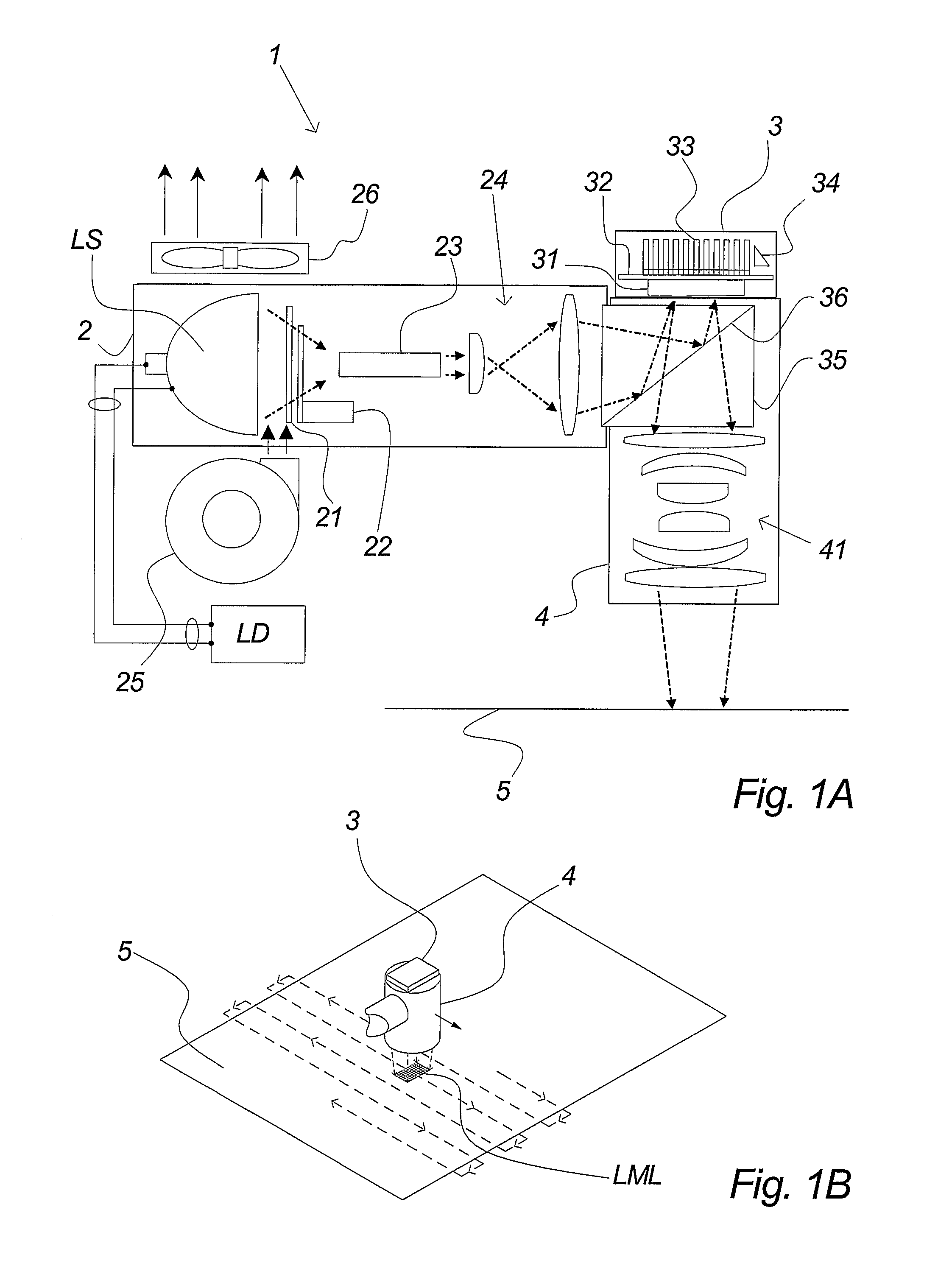
[0087]FIGS. 1A and 1B illustrate a preferred application of the present invention. FIG. 1A illustrates a light modulating arrangement 1 used for photolithography purposes, i.e., typically for exposing printing plates. A first part 2 of the arrangement 1 produces a focused and uniform beam of light. It comprises a light source LS, a lamp driver LD, a blower 25 and a fan 26, a protection glass and filter 21, a shutter 22, a light-integrating rod 23 and beam shaping optics 24.

[0088] The type of light source LS depends, among other things, on the type of plate to be exposed. Possible types comprise conventional short arc bulbs, laser sources, diode arrays and more. A preferred conventional lamp may have a power consumption of 270 W but the present invention is not in any way limited to this value or to the mentioned types of lamps. Alternatives such as 250 W and 350 W may, e.g., be considered.

[0089] The light from the light source LS is transmitted through a filter (e.g., IR or UV-fil...


PUM


Abstract

The invention relates to a method for enabling transmission of substantially equal amounts of energy from at least one light source (LS) comprising intensity variations in time to at least two light sensitive points (LSP), said transmission being controlled by means of at least one illumination arrangement (1), and said method comprising establishment of a correlation between said intensity variations and at least one feature of said illumination arrangement. The invention furthermore relates to an illumination arrangement (1) for controlling transmission of energy to at least two light sensitive points (LSP), wherein said controlling transmission enables transmission of substantially equal amounts of energy to each of said at least two light sensitive points (LSP).

Description

FIELD OF THE INVENTION [0001] The present invention relates to enablement of transmission of substantially equal amounts of energy to at least two light sensitive points, in the context of illumination arrangements comprising light sources with varying intensity. BACKGROUND OF THE INVENTION [0002] In several technical fields, illumination is either the main purpose or is used as a tool for obtaining desired results. Applications comprise, e.g., image and movie projection, photolithography, computer-to-plate applications, serigraphy, other photographical applications such as production of printed circuit boards, etc., photolysis, rapid prototyping, rapid manufacturing, communication, and several others. [0003] Numerous categories and types of light sources exist for illumination purposes, each manufactured with different purposes in view and often constrained to neglect other purposes. Purposes of interest may be power rating, luminous efficacy, stability of the luminous intensity, p...

Claims


Application Information

Patent Timeline
IPC IPC(8): G01J1/00B41J2/44B41J2/445G02B26/04G03F7/20G06K15/12
CPCB41J2/442G03F7/70291G03F7/70083
Inventor SEJERSEN, NIELS BORGBJERGLARSEN, NIELS HOLMGLENT-MADSEN, HENRIK
Owner SIGNTRONIC AG
Why Eureka
Try Eureka