Manipulator

a manipulator and handle technology, applied in the field of manipulators, can solve the problems of spatial limitation of attempts to increase the speed reduction ratio in the working unit, the difficulty of increasing the gripping force of the gripper, and the difficulty of reducing the diameter of the connector, so as to achieve the effect of small offset action and large gripping for

Active Publication Date: 2007-12-13
KARL STORZ GMBH & CO KG
View PDF15 Cites 450 Cited by
  • Summary
  • Abstract
  • Description
  • Claims
  • Application Information

AI Technical Summary

Benefits of technology

[0009]It is an object of the present invention to provide a manipulator which is capable of generating large gripping forces and which produces a small offset action when gripping a living body tissue.

Problems solved by technology

With the manipulator disclosed in Japanese Laid-Open Patent Publication No. 2003-61969, it is difficult to increase the gripping forces of the grippers.
However, these efforts make it difficult to reduce the diameter of the connector.
In addition, since various components for achieving movements about the respective axes need to be installed in the working unit which is of a small size, they pose a spatial limitation on attempts to increase the speed reduction ratio in the working unit.

Method used


Image

  • Manipulator
  • Manipulator
  • Manipulator

Examples


1st embodiment

[0036]A manipulator according to a first embodiment of the present invention will be described below with reference to FIGS. 1 through 7B.

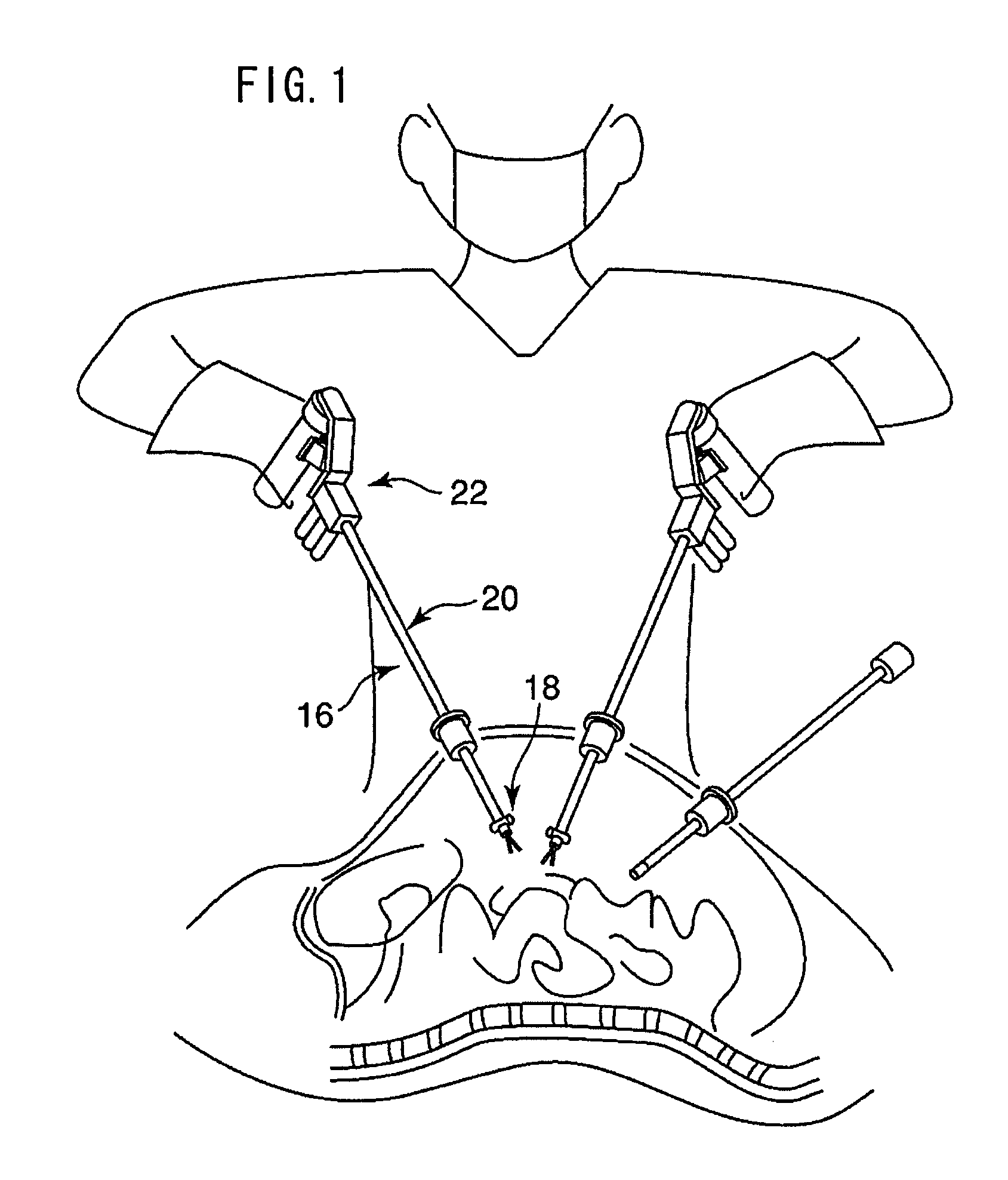
[0037]As shown in FIG. 1, a manipulator 16 according to the first embodiment of the present invention is a clip applier for applying clips. The manipulator 16 generally comprises a working unit 18 for medically treating or applying clips to a living body tissue, a slender connecting shaft 20, an operating unit 22 which is held and operated by the operator for actuating the working unit 18. The working unit 18, the connecting shaft 20, and the operating unit 22 are positioned successively from the distal end side of the manipulator 16.

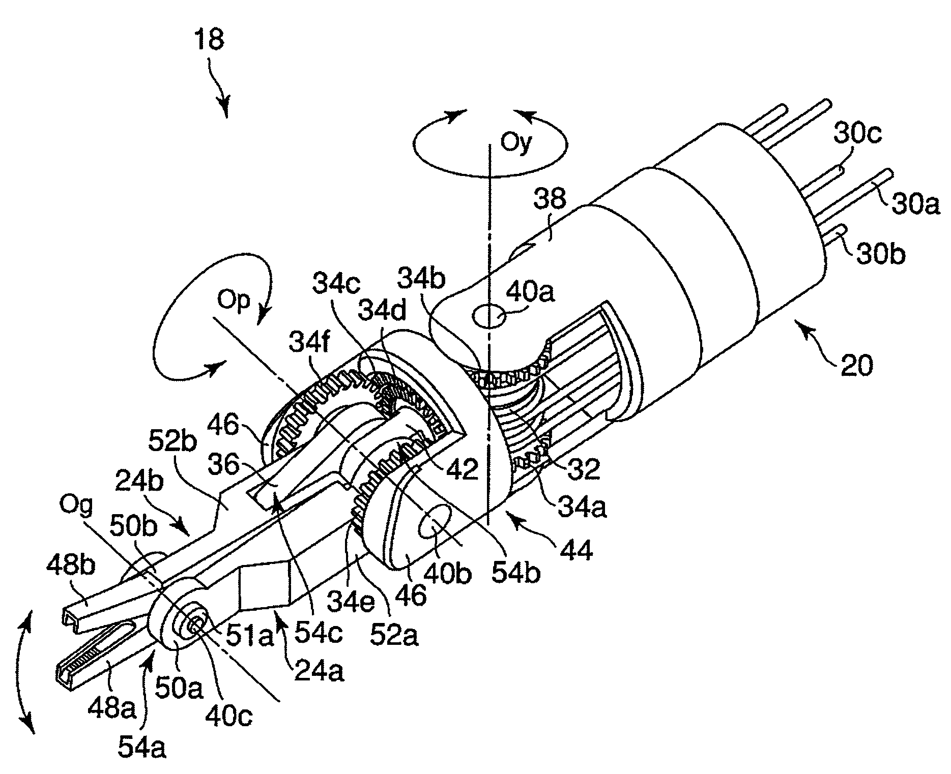
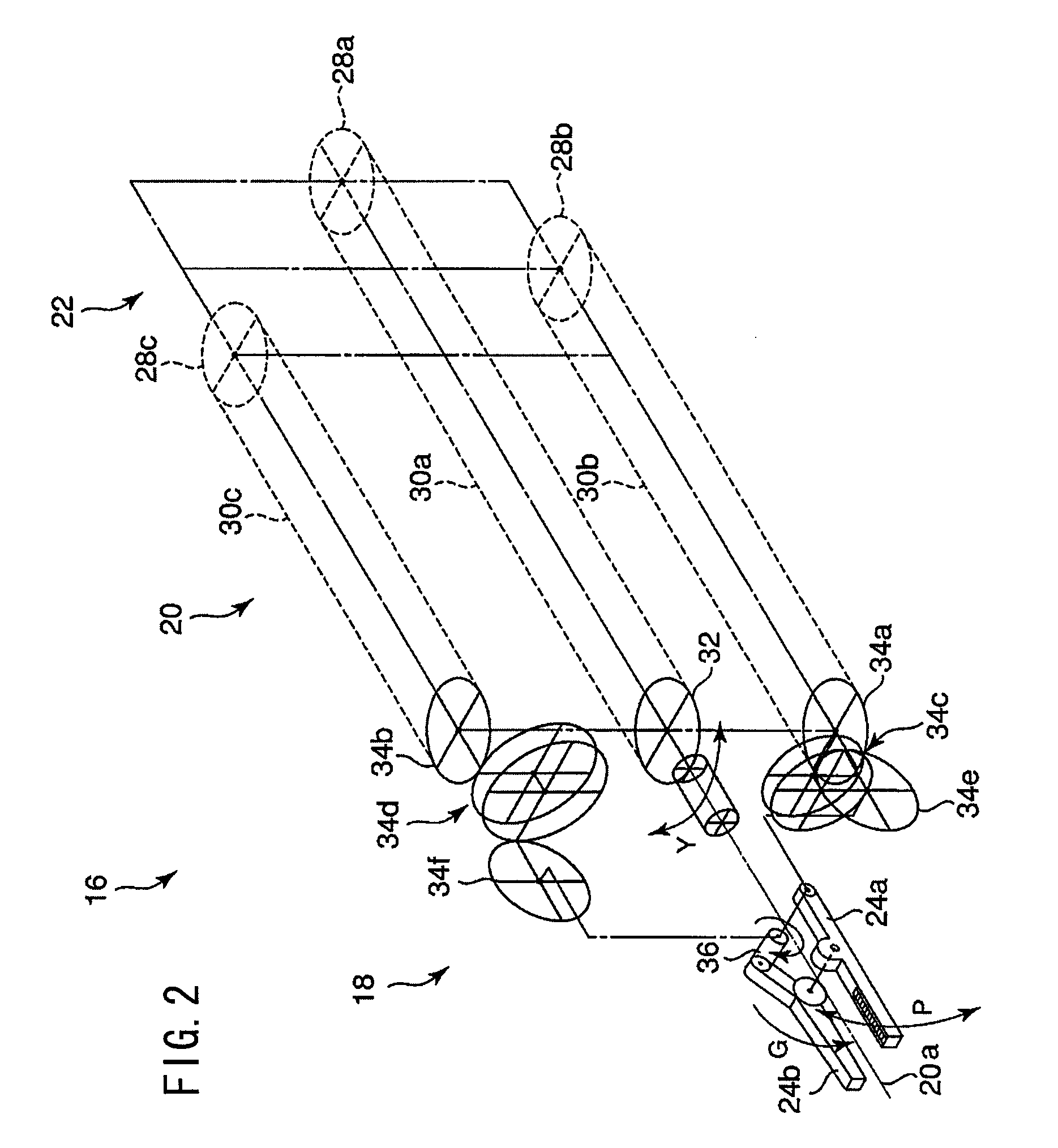
[0038]As shown in FIG. 2, the working unit 18 has a pair of first and second end effectors 24a, 24b angularly movable in the directions indicated by the arrow Y about a yaw axis which extends substantially perpendicularly to a main axis 20a of the working unit 18. The working unit 18 has a pulley 32 disposed therein, ...

2nd embodiment

[0089]FIGS. 8 through 9C show a manipulator 16 according to a second embodiment of the present invention. Those parts of the manipulator 16 according to the second embodiment which are structurally and functionally identical to those of the manipulator 16 according to the first embodiment are denoted by identical reference characters, and will not be described in detail below.

[0090]The manipulator 16 according to the second embodiment serves as scissors, and has first and second end effector fingers 48a, 48b in the form of respective cutting blades.

[0091]In a process of manufacturing scissors, it is important to perform mutual lapping on the cutting blades to provide sharp cutting edges. According to the second embodiment, mutual lapping is performed on first and second end effector fingers 48a, 48b in assembling the first end effector 24a, the second end effector 24b, and the third turn shaft 40c. Specifically, mutual lapping can easily be performed on first and second end effector...


PUM


Abstract

A manipulator has a working unit in which when at least a first end effector finger and a second end effector finger are maximally closed on each other, at least the distance between a third joint axis and a first joint axis is greater than the distance between the first joint axis and a distal end of the second end effector finger, or the distance between the third joint axis and the first joint axis is greater than the distance between third joint axis and a second joint axis, or the angle formed between a direction from the third joint axis to the first joint axis and a direction from the third joint axis to the second joint axis is not π.

Description

BACKGROUND OF THE INVENTION[0001]1. Field of the Invention[0002]The present invention relates to a manipulator for actuating a working unit by operating an operating unit.[0003]2. Description of the Related Art[0004]Heretofore, there has been used in the art an integral medical manipulator having an end working unit and a hand-operating unit which are connected to each other by a connector. Under endoscopic observation, the hand-operating unit is held by hand and operated to insert the end working unit into a body cavity and then actuate the end working unit to perform various medical treatments on the living body tissue.[0005]Japanese Laid-Open Patent Publication No. 2003-61969 discloses a manipulator having an operating unit and a working unit which incorporates in the operating unit a pair of grippers for gripping a living body tissue. The grippers can be opened and closed about a gripper shaft, and can be angularly movable in unison about a pitch axis and a roll axis. A wire is ...

Claims


Application Information

Patent Timeline
Patent Type & Authority Applications(United States)
IPC IPC(8): B25J17/02A61B17/06A61B17/12A61B17/3201B25J1/00
CPCA61B17/29A61B19/22A61B2017/2902A61B2017/2939A61B2017/2934A61B2017/2936A61B2017/2927A61B34/70
Inventor JINNO, MAKOTOSUNAOSHI, TAKAMITSUOMORI, SHIGERU
Owner KARL STORZ GMBH & CO KG
Why Eureka
Try Eureka