Camera

a technology for cameras and interlocking materials, applied in the field of cameras, can solve the problems that the interlocking material remains essentially limited to this container, and achieve the effects of short processing time, high production cost, and rapid hardening of interlocking materials

Inactive Publication Date: 2007-12-20
ROBERT BOSCH GMBH
View PDF2 Cites 16 Cited by
  • Summary
  • Abstract
  • Description
  • Claims
  • Application Information

AI Technical Summary

Benefits of technology

[0005] It is also particularly advantageous that the image converting element and / or the additional element of the camera includes at least one container because this contributes to a controlled introduction of the interlocking material during the manufacture of the camera. The interlocking material remains essentially limited to this container. Therefore, the risk of damage to or soiling of additional elements of the camera such as the optical elements is counteracted in an advantageous manner. Furthermore, the container has the advantage that only a small quantity of interlocking material, preferably 4 mm3 to 8 mm3, is required per interlocking operation. This also contributes to inexpensive manufacture of the camera.
[0006] It is advantageous that the interlocking material is solidified by ultraviolet radiation and / or the interlocking material includes at least two components that cooperate to cause the interlocking material to solidify and / or the interlocking material is solidified by cooling because interlocking materials having such properties are particularly suitable for manufacturing the camera because rapid hardening of the interlocking material is achieved and this contributes to a short processing time in the manufacture of the camera while such interlocking materials also ensure the long-term stability of the camera.
[0007] It is particularly advantageous that at least a portion of the surface of the image converting element and / or at least a portion of the surface of the additional element of the camera has elevations and / or depressions in the area of the interlock because elevations and / or depressions may be produced easily and inexpensively. It is particularly advantageous if the part of the inside surface of the housing that is used for interlocking has elevations and / or depressions. Alternatively or additionally, it is also advantageous if the part of the circuit board and / or the part of the circuit board frame that is used for interlocking has elevations and / or depressions. A stress-free connection is achieved by form-fitting without adhesion due to the distribution of the interlocking material in the cavity between the elevations and / or depressions.
[0008] A camera in which the image converting element and the additional element of the camera are additionally joined by an adhesive bond has the advantage that manufacturing the camera is simplified because the image converting element may be secured rapidly and reliably with the additional element of the camera by a fast-acting adhesive bond to then perform the permanent interlocking in a second method step. In addition, it is advantageous to use the adhesive bond for a permanent connection because the stability of the configuration of the camera for ongoing operation and the service life of the camera are additionally increased.
[0009] An extremely small distance between the image converting element and the additional element of the camera in the area of the interlock between 0.5 mm and 3.5 mm contributes in an advantageous manner to a particularly high stability of the configuration of the camera. Furthermore, this permits a particularly compact and thus space-saving configuration of the camera.
[0010] It is advantageous if the image converting element includes at least one image sensor and / or at least one circuit board and / or at least one circuit board frame. It is particularly advantageous here if the image converting element is connected to the at least one other element of the camera, e.g., the housing and / or the optical unit, by at least one interlock via the circuit board frame because this results in a particularly stable configuration of the camera which is therefore suitable for automotive engineering. Alternatively or additionally, the circuit board is connected directly to the at least one additional element of the camera, for example the housing and / or the optical unit, by at least one interlock, because a circuit board frame may then be omitted and the camera is compact, lightweight, and inexpensive.

Problems solved by technology

The interlocking material remains essentially limited to this container.

Method used


Image

  • Camera
  • Camera
  • Camera

Examples


Embodiment Construction

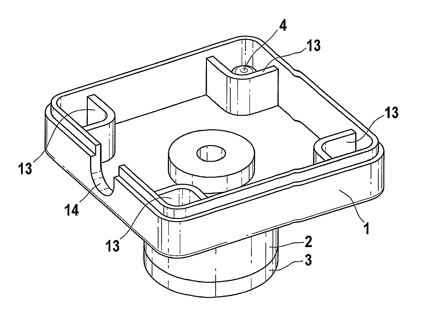
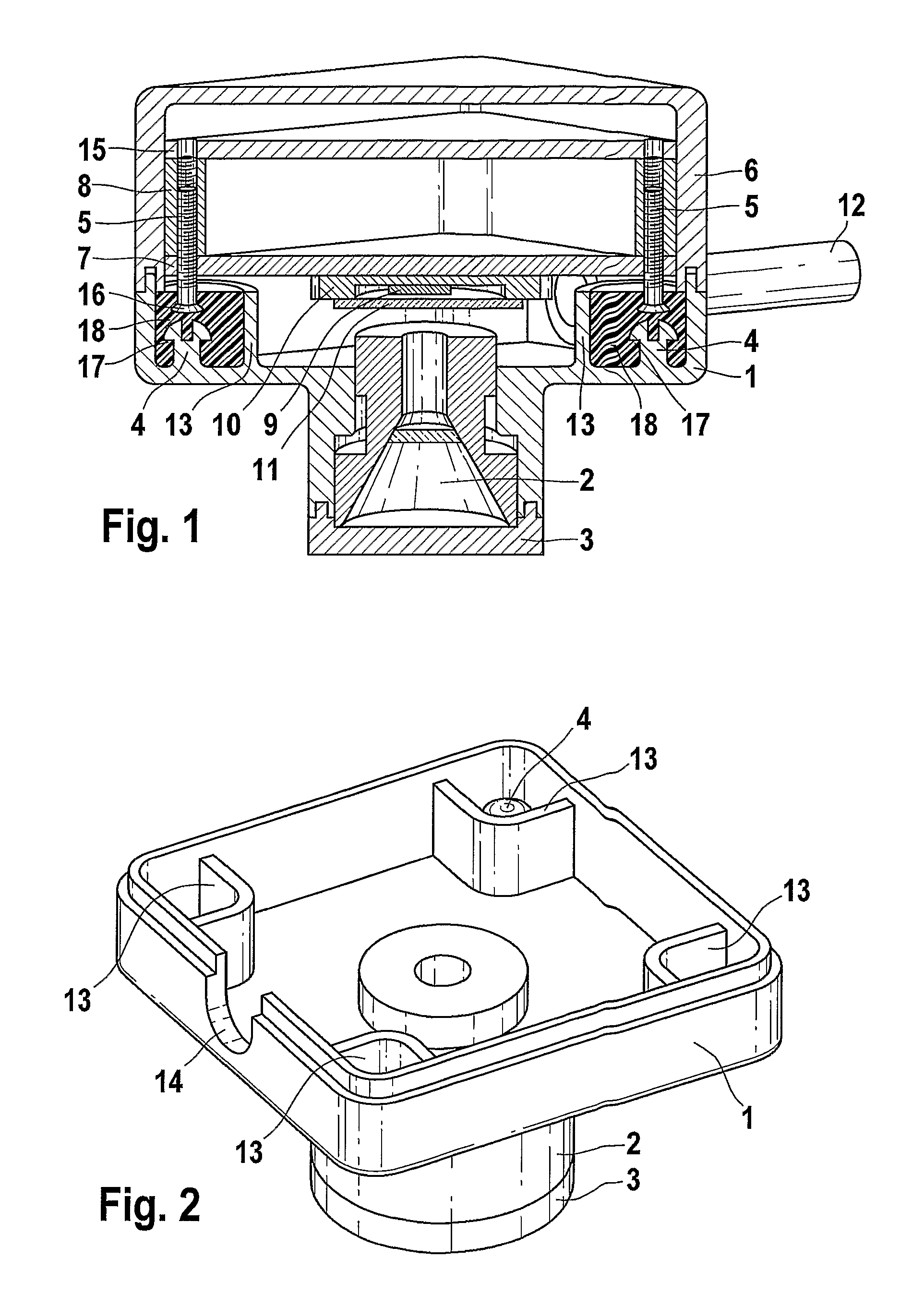
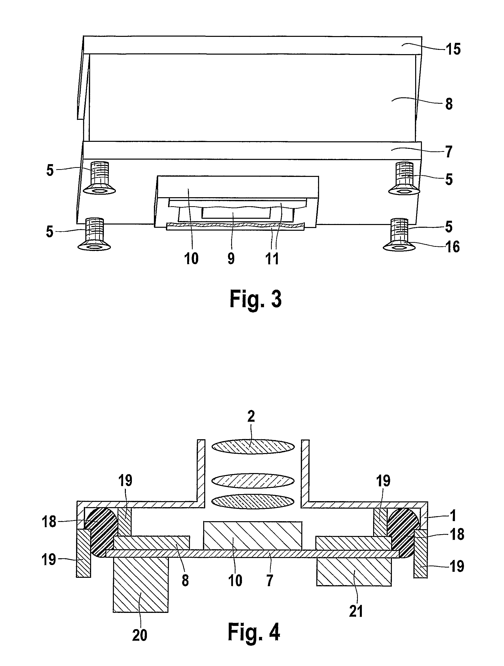
[0015] A camera, in particular for a motor vehicle, having at least one image converting element is provided. The image converting element includes at least one image sensor and is connected to at least one other element of the camera, e.g., the housing of the camera, by at least one interlock.

[0016] Cameras for automotive use must be very sturdy and at the same time very accurate on the one hand while on the other hand they must be inexpensive. It is conceivable to achieve a high precision through additional design complexity. Possible solutions to this problem include pins, stop edges, or high-precision tolerances. These solutions are associated with increased costs. These costs are necessary for the operation of assembly of the camera to achieve a high precision but are not essential for use of the camera and are simply carried over there.

[0017] In the camera of the preferred exemplary embodiment as described below, an interlocking material is used for joining a circuit board l...


PUM


Abstract

A camera in particular for a motor vehicle having at least one image converting element. The image converting element includes at least one image sensor and is connected to at least one additional element of the camera, e.g., the housing of the camera, by at least one interlock.

Description

BACKGROUND INFORMATION [0001] German Patent No. DE 40 32 927 describes a camera in a motor vehicle. This camera is used to improve visibility conditions and is therefore mounted in an area of the inside rear view mirror for detecting the viewing range of the driver in the direction of travel. SUMMARY OF THE INVENTION [0002] The camera according to the present invention, in particular for a motor vehicle, has the advantage that a simple design of the camera is achieved with a high precision of the camera design at the same time. Furthermore, the camera has the advantage that the configuration is sturdy so the configuration is not sensitive to vibrations and temperature fluctuations. In addition, the camera is inexpensive to manufacture. Furthermore, the connection of the image converting element to another element of the camera through at least one interlock has the advantage that manufacturing tolerances in the components are easily compensatable by the interlock. This has the advan...

Claims


Application Information

Patent Timeline
Patent Type & Authority Applications(United States)
IPC IPC(8): G03B17/56H04N5/225
CPCH04N5/2254H04N5/2253H04N23/55H04N23/54H04N23/00
Inventor GOTTWALD, FRANKKNEE, WERNERUFFENKAMP, VOLKERSCHICK, JENS
Owner ROBERT BOSCH GMBH
Why Eureka
Try Eureka