Tip Turbine Engine Comprising Turbine Blade Clusters and Method of Assembly
- Summary
- Abstract
- Description
- Claims
- Application Information
AI Technical Summary
Benefits of technology
Problems solved by technology
Method used
Image
Examples
Embodiment Construction
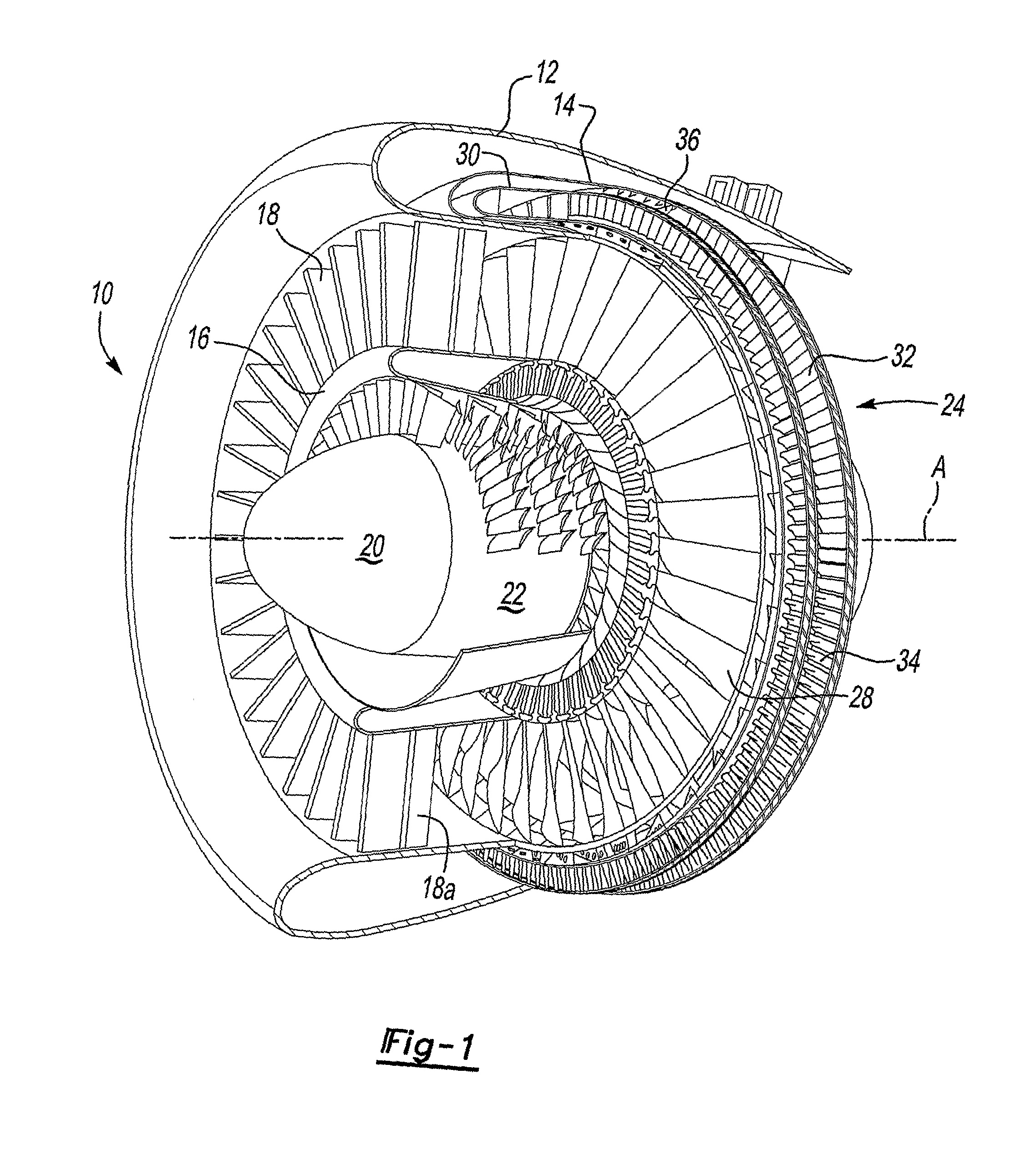
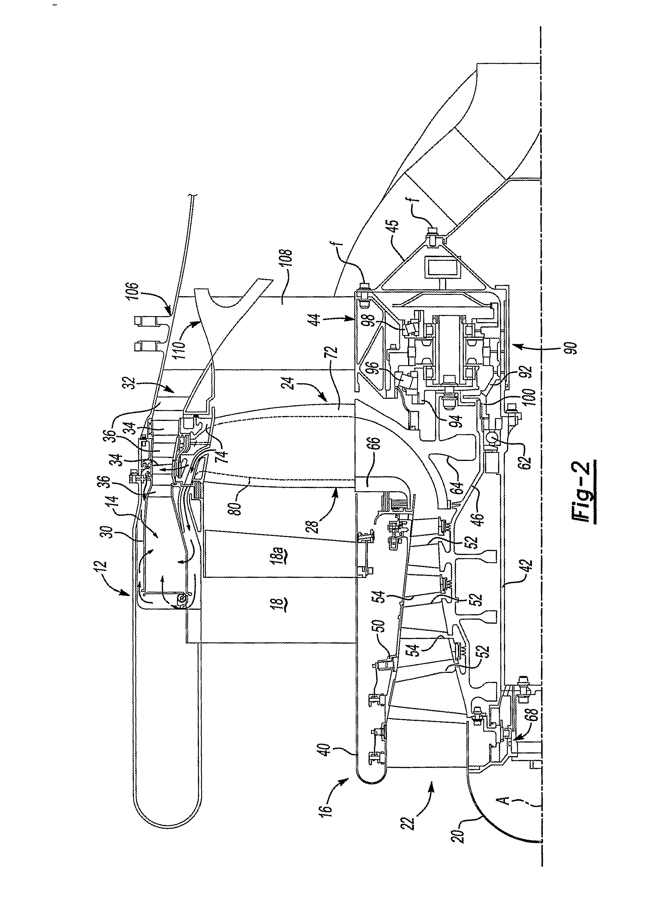
[0030]FIG. 1 illustrates a general perspective partial sectional view of a tip turbine engine type gas turbine engine 10. The engine 10 includes an outer nacelle 12, a nonrotatable static outer support structure 14 and a nonrotatable static inner support structure 16. A multitude of fan inlet guide vanes 18 are mounted between the static outer support structure 14 and the static inner support structure 16. Each inlet guide vane preferably includes a variable trailing edge 18A.
[0031] A nose cone 20 is preferably located along the engine centerline A to smoothly direct airflow into an axial compressor 22 adjacent thereto. The axial compressor 22 is mounted about the engine centerline A behind the nose cone 20.
[0032] A fan-turbine rotor assembly 24 is mounted for rotation about the engine centerline A aft of the axial compressor 22. The fan-turbine rotor assembly 24 includes a multitude of hollow fan blades 28. The hollow fan blades 28 communicate this compressed air from the axial c...
PUM
 Abstract
Description
Claims
Application Information
 - R&D
- Intellectual Property
- Life Sciences
- Materials
- Tech Scout
- Unparalleled Data Quality
- Higher Quality Content
- 60% Fewer Hallucinations
Browse by: Latest US Patents, China's latest patents, Technical Efficacy Thesaurus, Application Domain, Technology Topic, Popular Technical Reports.
© 2025 PatSnap. All rights reserved.Legal|Privacy policy|Modern Slavery Act Transparency Statement|Sitemap|About US| Contact US: help@patsnap.com


