
In-situ temperature detection in high temperature ceramic structures

a ceramic structure and in-situ temperature detection technology, applied in catalyst activation/preparation, machine/engine, surface coverings, etc., can solve the problems that the extensive bench testing instrumentation used to determine peak filter temperature and temperature gradient cannot be practically employed to measure or control the regeneration cycle of operating motor vehicles, and achieves low monitoring cost, cost-effective, and easy installation and maintenance.

Inactive Publication Date: 2007-12-20
CORNING INC
View PDF16 Cites 11 Cited by
  • Summary
  • Abstract
  • Description
  • Claims
  • Application Information

AI Technical Summary

Benefits of technology

[0013]Pre-selected materials with suitable phase change temperatures may be added to the washcoat slurries used to coat such structures without any change in washcoating processes. Thus the invention obviates the need for thermocouples distributed through the structure that are relatively expensive to install and maintain, and that may unfavorably influence gas flow and / or temperature profiles across the structures. An additional advantage is that no changes to the engine control systems are needed for implementation of the invention.
[0014]Suitable phase change materials for use in accordance with the invention include inorganic materials exhibiting irreversible and detectable changes in attributes such as physical properties, chemical states, or physical states upon heating to temperatures within the operating ranges of ceramic substrates or filters. Thus when the temperature in a region of the ceramic structure is elevated beyond a transition temperature at which such a phase change will occur, the material attributes of the phase changed material(s) are irreversibly altered and the thermal history of the structure is thereby recorded for tracing in post-analyses involving either destructive or non-destructive testing methods. For example, a phase transition that is detectable by an X-ray diffraction analysis of the amorphous or crystallized material subsequent to a high temperature exposure is one suitable method for determining the minimum temperature to which the diffraction sample has been heated. Similarly, the use of multiple phase change materials in such samples can establish ranges of temperature for previous high temperature exposures.
[0015]The thermal history of a structure as determined by the above described methods can be effectively used to map the thermal profiles that may have been developed in such substrates or filters in use. Determining such profiles can help to establish whether structural failures in such structures resulted from thermal stresses, or instead from simple mechanical causes.
[0016]In summary, then, the present invention effectively provides: an in-situ monitoring system for the thermal history of a high temperature substrate; low monitoring cost due to the need for only small quantities of inexpensive phase-change materials; ease of ceramic manufacture due to the ease of incorporating phase change materials into coatings or batches; the ready availability of conventional and proven analytical methods and systems for the evaluation of phase changes in the incorporated materials; the absence of any adverse impact on gas flow within the channels of structures incorporating phase change materials; and the adaptability of the method to the use of on-line detection systems. Thus the invention provides cost-effective and highly efficient operating temperature determination methods when compared with known prior art procedures.

Problems solved by technology

Over time, the particulates collected by the filter increase pressure drop across the filters and thus exhaust gas back-pressure within the engine exhaust system.
Instrumentation at these levels has confirmed that different locations within such filters reach different temperatures during regeneration, in some cases resulting in large temperature gradients within the filters and in others resulting in damage to the ceramic structure itself.
Unfortunately, however, the extensive bench testing instrumentation used to determine peak filter temperatures and temperature gradients cannot be practically employed to measure or control the regeneration cycle in operating motor vehicles.
Accordingly, there is no practical way of determining whether or when the design limits for long-term filter operation might have been exceeded during vehicle operation.

Method used


Image

  • In-situ temperature detection in high temperature ceramic structures
  • In-situ temperature detection in high temperature ceramic structures

Examples


Embodiment Construction

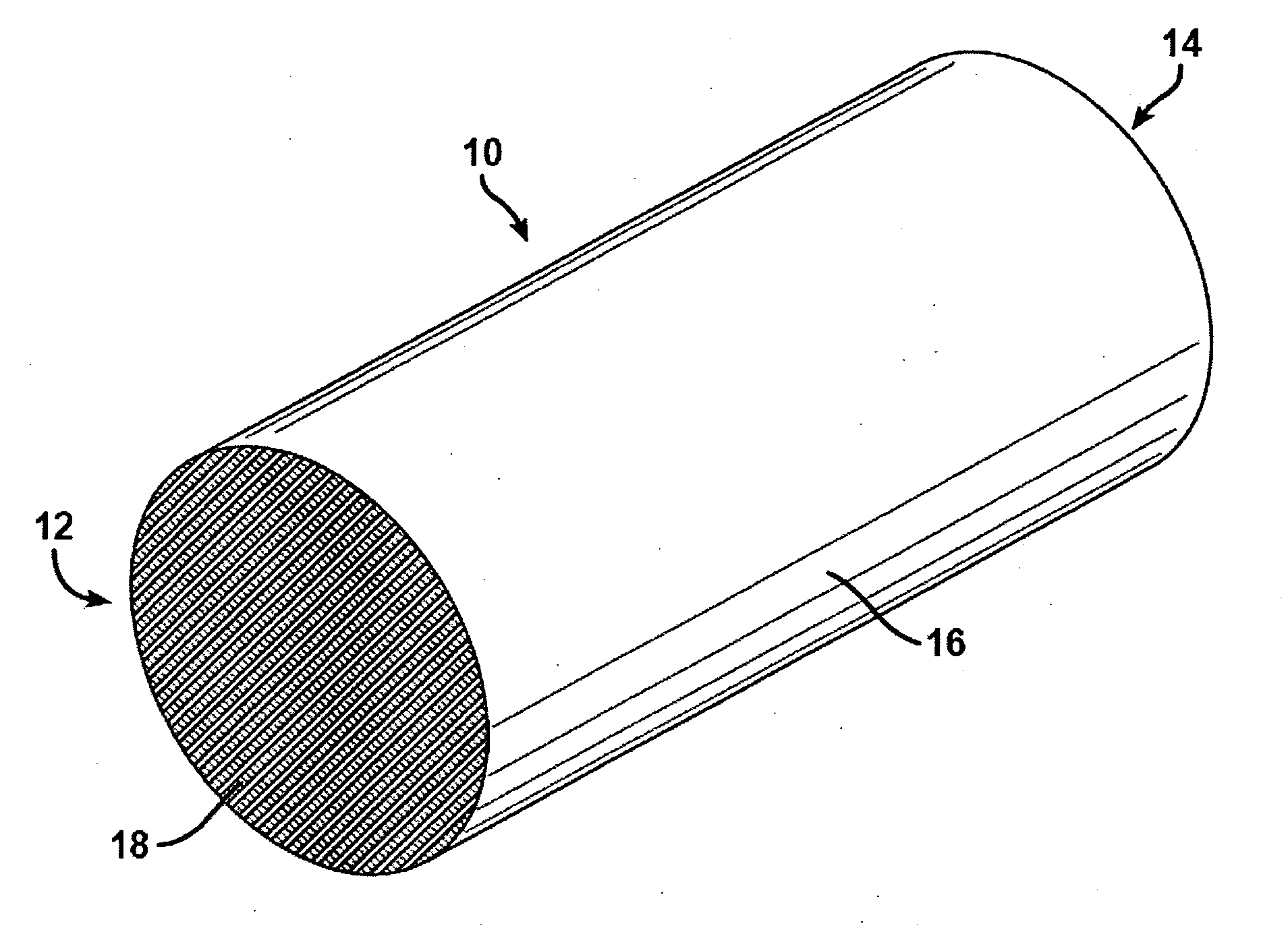
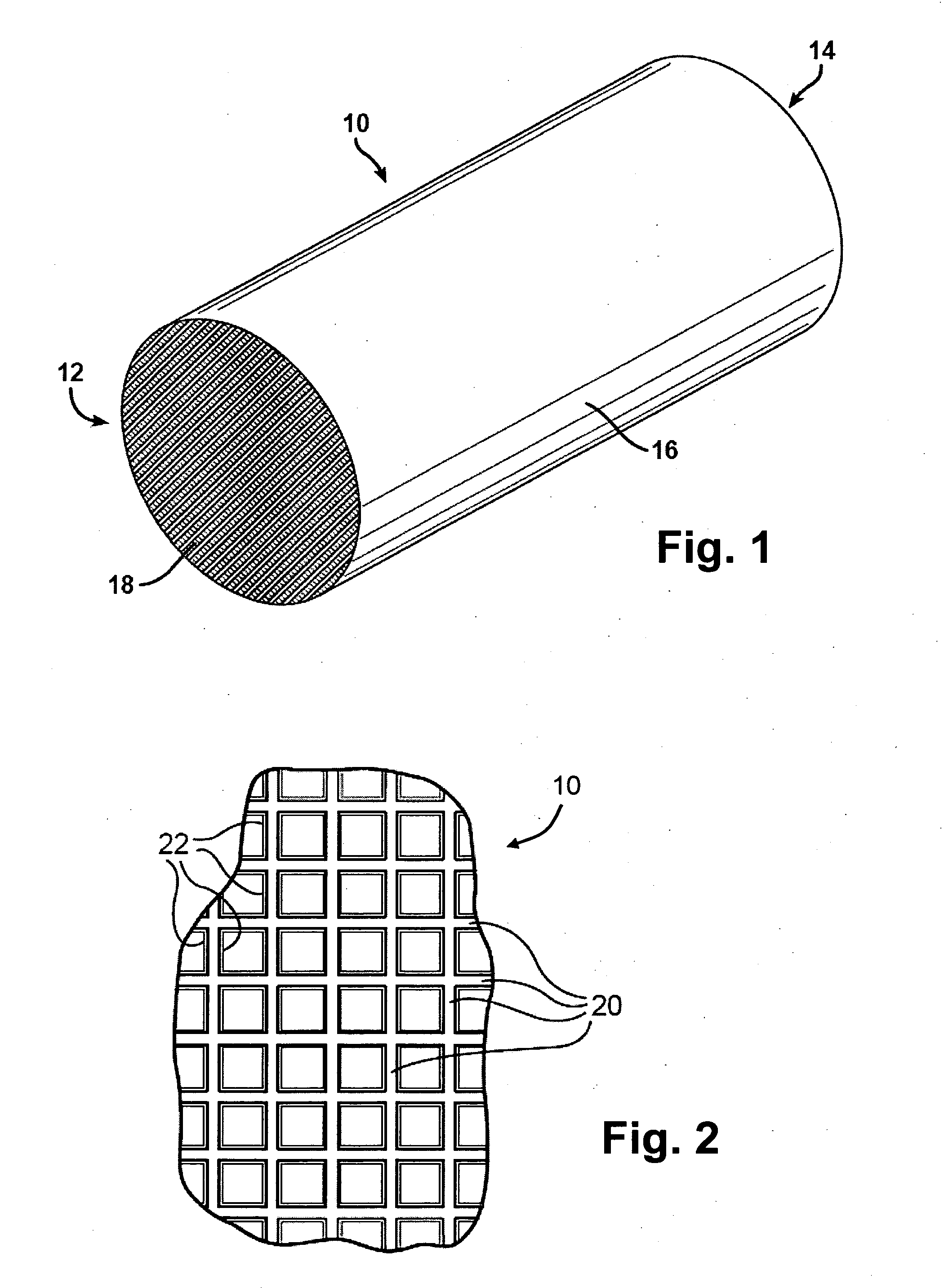
[0019]A high temperature ceramic structure in the form of a porous ceramic honeycomb 10 provided according to the present invention is schematically illustrated in FIG. 1 of the drawings. Honeycomb structure 10 is composed of a body 16 having an inlet end 12, an outlet end 14, and a plurality of channels 18 extending in parallel between the inlet end 12 and the outlet end 14 of the body. For use as a diesel particulate filter, body 16 would further comprise an alternating pattern of plugs (not shown) disposed within alternate channels 18 on inlet end 12 and outlet end 14 of body 16, arranged in known fashion so that exhaust gases are forced through the porous walls 20 of the channels 18 in traversing the body from its inlet to its outlet.

[0020]Honeycomb structure 10 may be formed of any channel density; for example channel densities in the range of 100-400 channels per square inch of honeycomb cross-section are suitable for the construction of diesel engine exhaust filters, while de...


PUM

PropertyMeasurementUnit
temperatureaaaaaaaaaa
temperaturesaaaaaaaaaa

Abstract

Ceramic structures such as catalyst supports or combustion exhaust filters that incorporate combinations of high temperature phase change materials, and methods for determining the thermal history of such ceramic structures, by disposing the phase change materials on or within the structures and subsequently detecting the presence or absence of phase changes in the materials after exposure to high temperatures.

Description

FIELD OF THE INVENTION[0001]The present invention enables the collection of operating condition information attending the use of high temperature ceramic structures as catalyst supports and / or exhaust filters for the treatment of exhaust gases from carbonaceous fuel combustion processes. It is particularly adaptable for use with ceramic structures such as diesel particulate wall flow filters (DPFs) used for the removal of soot and other particulates from diesel engine exhaust gases.BACKGROUND OF THE INVENTION[0002]Diesel engines are a target of increasing development activity by combustion engine and motor vehicle manufacturers because they offer the potential for lower emissions and increased fuel economy as compared to gasoline engines. Diesel particulate filters (DPFs) are being developed as components of diesel engine exhaust systems in order to control particulate exhaust emissions by physically trapping soot particles present in exhaust steam in their structure. Among the dies...

Claims


Application Information

Patent Timeline
Patent Type & Authority Applications(United States)
IPC IPC(8): B32B3/12B32B3/26
CPCB01J35/04Y10T428/24496C04B41/009C04B41/5027C04B41/87C04B2111/0025C04B2111/00793C04B2111/0081F01N11/00F01N2330/06F01N2510/00B01J37/0215Y10T428/24149Y02T10/47C04B35/00C04B35/195C04B35/185C04B35/565C04B35/584C04B35/478C04B38/0006Y02T10/40B01J35/56
Inventor SORENSEN, CHARLES MITCHELTAO, TINGHONGWEN, BIN
Owner CORNING INC
Features
  • Generate Ideas
  • Intellectual Property
  • Life Sciences
  • Materials
  • Tech Scout
  • Unparalleled Data Quality
  • Higher Quality Content
  • 60% Fewer Hallucinations
Learn More