Dust separation system for use with mobile equipment

a technology for dust separation and mobile equipment, which is applied in the direction of auxillary pretreatment, cleaning filter means, separation processes, etc., can solve the problems of modest improvement in filter life, inability to fully capture dust and debris, and inability to exhaust fine particulate matter due to incomplete capture, etc., to achieve high flow rate, increase both flow resistance and collection efficiency, and improve the effect of collecting efficiency

Inactive Publication Date: 2007-12-27
FEDERAL SIGNAL CORPORATION
View PDF12 Cites 20 Cited by
  • Summary
  • Abstract
  • Description
  • Claims
  • Application Information

AI Technical Summary

Benefits of technology

[0014] Key operating parameters of an axial cyclone, including the collecting efficiency and the pressure drop, are governed at least in part by the dimensions, namely the cross sectional areas and lengths of the unit. The diameter of a cyclone strongly influences its collecting efficiency. Smaller diameters provide greater collecting efficiency. The dust discharge opening should be as small as possible, in order to maintain a high rate of flow therethrough to forestall clogging. Cyclone overall length affects not only flow resistance but also collecting efficiency. Increasing cyclone overall length will increase both its flow resistance and collecting efficiency. The cyclones used in the present invention preferably are operated at or above five (5) feet per second (FPS) of air flow. This operational threshold is dependent on the particular attributes of the axial cyclones used. It will be understood that the monitoring of air flow through the system of axial cyclones is used in controlling the system to maintain optimal air flow through each of the array of axial cyclones. In other words, when the amount of air flow through the particular axial cyclone is determined, this value may be used as a threshold or trigger in controlling the system. When the air flow drops below the threshold, one or more cyclone is shuttered by closing an appropriate valve and air flow should increase or be maintained in the remaining cyclone(s) at a predetermined level. When air flow through the system increases to a value above the threshold, the system may open one or more additional cyclone valve to permit an increase in the amount of air flow through the system.

Problems solved by technology

However, lighter debris particles may tend to remain in the air stream and continue to move toward the blower and the exhaust where the dust may be released to the environment as part of the exhaust air from the air stream.
Of course, exhausting fine particulate matter as a result of the incomplete capture of dust and debris is not acceptable.
While generally effective at removing debris particles from the air stream, filter bags and sock filters can become clogged quickly and, accordingly, must be cleaned and / or replaced frequently, when brought into contact with many types of airborne debris particles.
Unfortunately, in practice most shaker and agitator systems have been shown to make only modest improvements in filter life.
Moreover, such systems may require a large number of mechanical and / or pneumatic components and thereby increase the cost of the system as well as the likelihood of system failure.
So, it can be seen that these adaptations, while effective, tend to add complexity and cost to the system and maintenance of the system.
While effective in many respects, the effective filter life and efficiency in such serial cyclone separator / bag-house filter systems still often remains shorter than the period of desired operation.
Tangential cyclones tend to be bulky devices, necessitating a relatively large amount of space to accommodate them.
Use of this technique alone does not address fine airborne dust.
While effective, using a water spray or mixing system necessarily requires the carrying of a sufficient amount of water onboard.
Naturally, this increases the weight and complexity of the vehicle and may impose limits as to its operation.

Method used


Image

  • Dust separation system for use with mobile equipment
  • Dust separation system for use with mobile equipment
  • Dust separation system for use with mobile equipment

Examples


Embodiment Construction

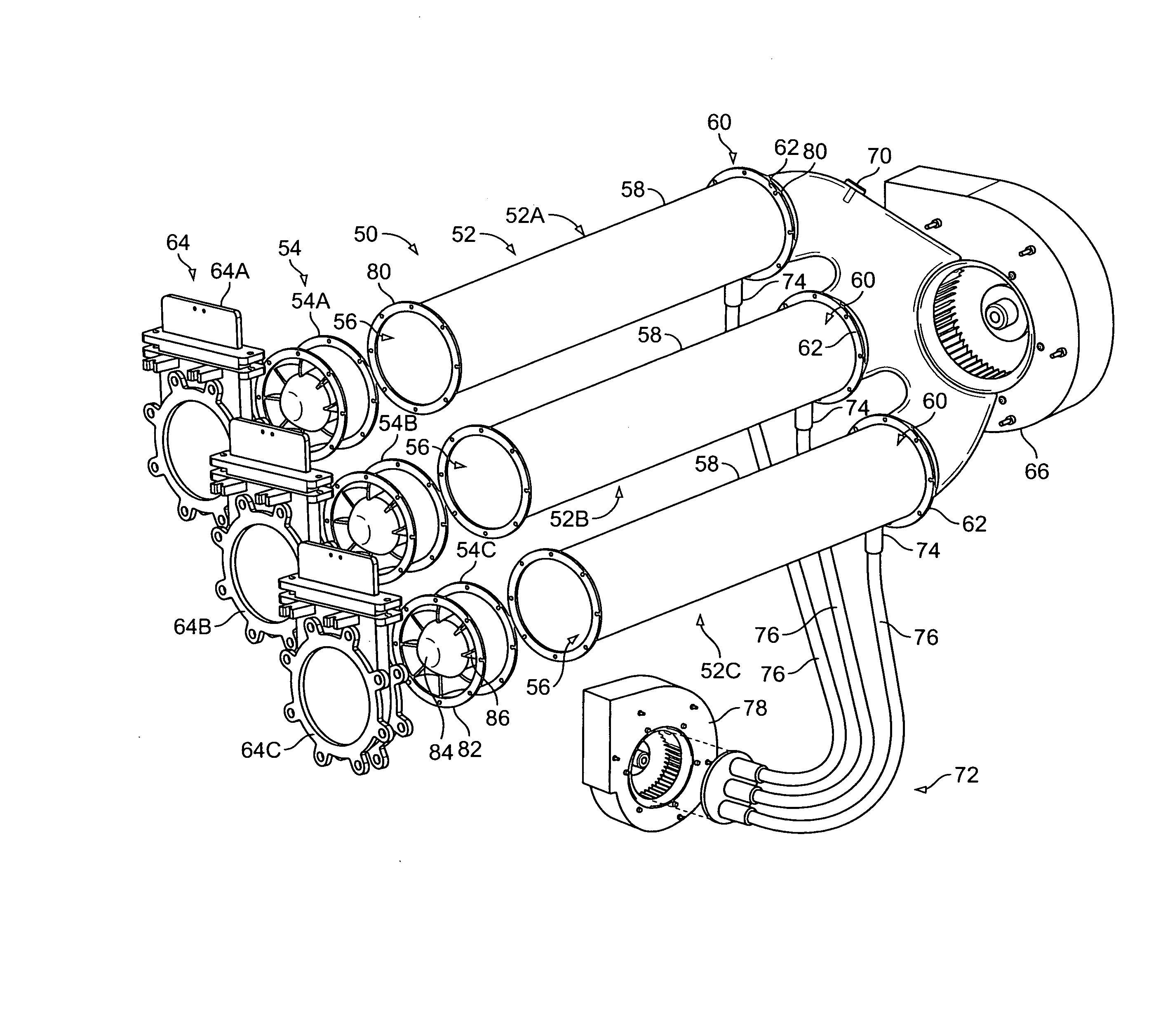
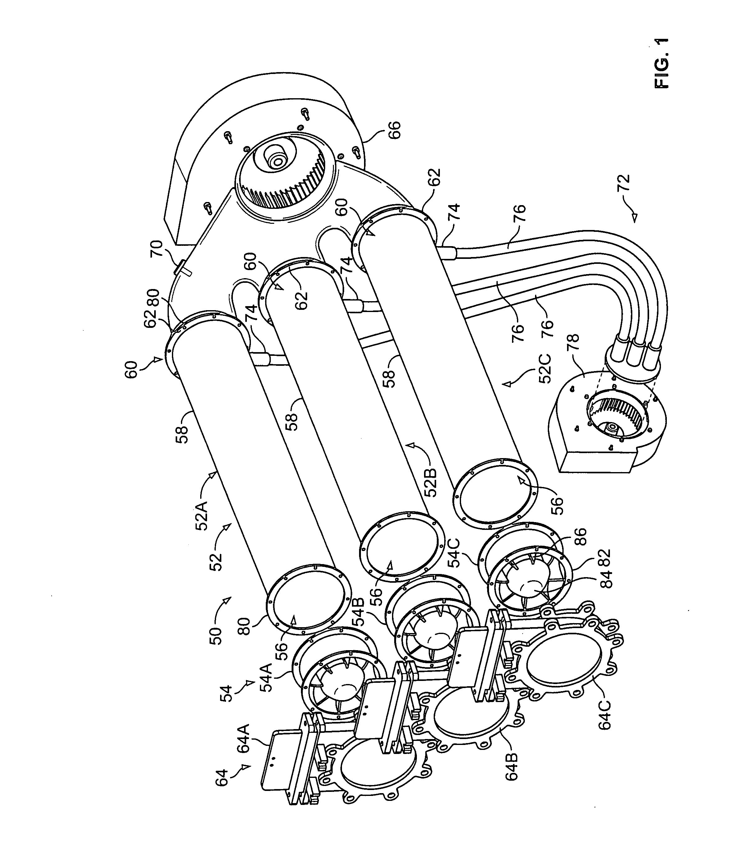
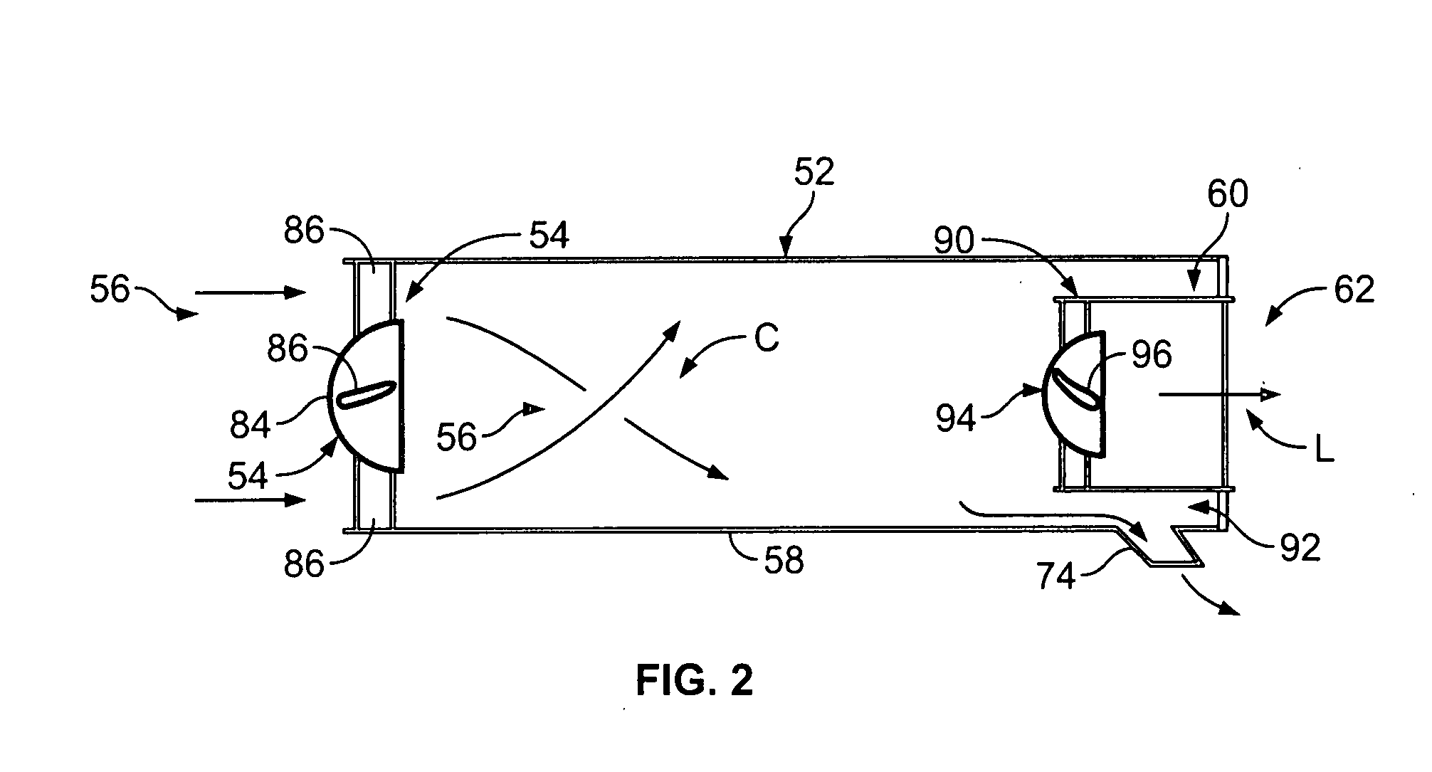
[0019] Embodiments of the invention described herein may be used with commercially available cleaning or sweeping vehicles, for example, wherein dust removal from an air flow is desired. It will be understood that any suitable vehicle, which performs cleaning, sweeping, vacuuming or acquisition of particulate matter, fluids and the like, will benefit from embodiments of the present invention. Different sized and shaped dust separation systems may be employed dependent upon the functional parameters of the device to which the system will be attached, as well as the provision of ductwork or passages to couple the dust removal system to the other structural and functional aspects of the vehicle. Furthermore, it will be understood that the operating parameters discussed herein are exemplary in nature and not to be construed as limiting. Air flow thresholds, in particular, will be dependent upon the size and shape and number of axial cyclones used in the array, the vacuum-generating devi...


PUM

PropertyMeasurementUnit
lengthaaaaaaaaaa
pressureaaaaaaaaaa
weightaaaaaaaaaa

Abstract

Embodiments of the invention include a dust extraction system including an array of two or more centrifugal dust removal devices, e.g., axial cyclones. The array of axial cyclones is configured to operate in parallel. The array of axial cyclones includes one or more sensor and a controller in communication with the sensor and adapted to receive air flow information from the one or more sensor. Inflow valves are operatively connected to the controller such that air flow through the array of axial cyclones is monitored and maintained at an optimum operating condition for each of the individual cyclones in the array. This is done, in general, by opening inflow valves as the air flow increases above a predetermined air flow value and shutting inflow valves as air flow decreases below the predetermined air flow value threshold.

Description

[0001] This application claims the benefit of U.S. provisional application No. 60 / 800,363, filed May 15, 2006.FIELD OF THE INVENTION [0002] This invention pertains generally to dust separation systems and mobile sweeping, cleaning and conveying equipment, and the like, including such systems. In particular, embodiments of dust separation systems according to the invention are intended for use with mobile cleaning equipment such as mobile vacuum air sweepers or street sweepers, mobile sewer cleaners, mobile industrial vacuum loaders, i.e., mobile pneumatic conveyance equipment, and the like. More particularly, the invention is directed to the use of a plurality of axial cyclone separators or devices for removing debris and / or dust in a mobile cleaning vehicle. The axial cyclone separators are controlled during operation of the vehicle to remove detritus including particulate matter from air flowing through the system to maintain optimal operating efficiency of the axial cyclone devic...

Claims


Application Information

Patent Timeline
Patent Type & Authority Applications(United States)
IPC IPC(8): B01D45/12A47L9/10B04C1/00
CPCB01D45/16B04C3/04B04C2009/005B04C2003/006B04C11/00
Inventor STRAUSER, DANIEL P.
Owner FEDERAL SIGNAL CORPORATION
Why Eureka
Try Eureka