Thin liquid crystal display backlight illumination system with directivity

A liquid crystal display and backlighting technology, applied in the direction of nonlinear optics, optics, instruments, etc., can solve the problems of reducing system thickness, uneven brightness, large brightness loss, etc., and achieve the effect of low price, uniform brightness, and less light loss

Inactive Publication Date: 2021-01-19
东莞广辰光电科技有限公司
View PDF5 Cites 0 Cited by
  • Summary
  • Abstract
  • Description
  • Claims
  • Application Information

AI Technical Summary

Problems solved by technology

This lighting design can form an ideal lighting source with a uniform and moderate diffusion angle on the light-emitting surface (that is, the surface of the lens array), so that no light guide column is required and the thickness of the system is reduced. However, in the actual production process, due to the limitations of the mold and the process, The connection between each lens on the lens array 71 will produce an arc-shaped junction area 710 due to the height difference of the lenses. When the lens array 71 is composed more, the unit shadows 722 formed in the unit light areas 721 can also be connected to each other, so that the lengths L1 and L2 of the shadows appearing in the light projection light area 72 are longer, which also results in obvious brightness The disadvantage of unevenness is that this structure is difficult to break through
[0006] The design of the above-mentioned commonly used backlight lighting system has not been perfected, and it has the disadvantages of large volume, large brightness loss, uneven brightness, and high cost. It is inconvenient to use in occasions with limited space, such as the head-up display of a car.

Method used


Image

  • Thin liquid crystal display backlight illumination system with directivity
  • Thin liquid crystal display backlight illumination system with directivity
  • Thin liquid crystal display backlight illumination system with directivity

Examples


Embodiment Construction

[0038] The present invention will be described in further detail below in conjunction with the accompanying drawings and specific embodiments, and the implementation scope of the present invention is not limited thereto.

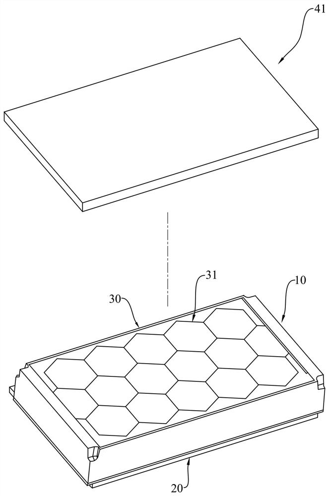
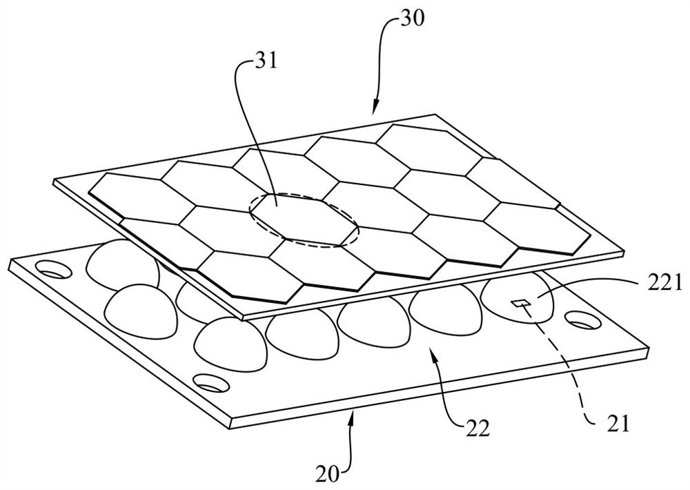
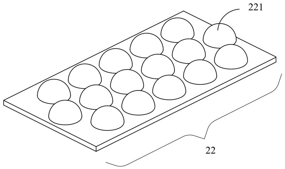
[0039] like Figure 1 to Figure 10As shown, a directional thin liquid crystal display backlight lighting system described in this embodiment includes a base 10, a circuit board 20, a condenser lens group 22 and an array lens (Array lens) 30, on the base 10 is provided with an accommodating space, the circuit board 20 is fixed on the bottom of the accommodating space of the base 10, and a plurality of illuminants 21 are arranged on the circuit board 20, preferably, the illuminants 21 are white light emitting diodes , the luminous brightness is strong, and the emitted light can be emitted forward. The condensing lens group 22 is installed in the accommodating space and is located above the circuit board 20. The condensing lens group 22 includes a plurality of ...


PUM


Abstract

The invention discloses a thin liquid crystal display backlight illumination system with directivity, which comprises a base, a circuit board, a condensing lens group and an array lens, an accommodating space is arranged in the base, the circuit board is arranged at the bottom of the accommodating space of the base, a plurality of illuminants are arranged on the circuit board, and the array lens is arranged in the accommodating space of the circuit board. The condensing lens group is arranged in the accommodating space and located above the circuit board, the condensing lens group comprises aplurality of condensing lenses, each condensing lens is arranged corresponding to each luminous body, the array lens is arranged at the top of the accommodating space of the base and located above thecondensing lens group, the array lens comprises a plurality of Fresnel lens units, and the Fresnel lens units are arranged in the accommodating space of the base. Each Fresnel lens unit is arranged corresponding to each condensing lens, and the sawtooth height of the section of each Fresnel lens unit is smaller than 50 microns; and according to the backlight illumination system, the backlight effect with high brightness and uniform brightness can be achieved, a common light guide column and diffusion sheet structure is omitted, the light loss is small, the brightness is higher, the cost is saved, and the thickness is smaller.

Description

technical field [0001] The invention relates to the technical field of backlight lighting systems, in particular to a directional thin liquid crystal display backlight lighting system. Background technique [0002] Common liquid crystal displays, such as mobile phones, tablets, TVs and other devices, the backlighting system, mostly the light source passes through the structure of the light guide plate and the diffusion sheet to form a light source with diffuse direction and uniform surface, and then passes through the front liquid crystal display The advantage of this kind of backlighting is that it allows users to see the image content of the LCD display clearly from various angles, but its disadvantage is that the direction of the illumination light is too scattered, and it is easy to see in a bright outdoor environment. As a result, the brightness is insufficient and the image cannot be seen clearly; at this time, the brightness must be increased, which in turn will cause...

Claims


Application Information

Patent Timeline
Patent Type & Authority Applications(China)
IPC IPC(8): G02F1/13357G02B1/04G02B3/08
CPCG02F1/133606G02F1/133603G02B1/041G02B3/08
Inventor 孙国魁吕和
Owner 东莞广辰光电科技有限公司
Why Eureka
Try Eureka