
Solar assembly with a multi-ply barrier layer and individually encapsulated solar cells or solar cell strings

a solar cell and barrier layer technology, applied in the field of solar cells, can solve the problems of not being able to pass light sufficiently, affecting the performance of solar cells and solar cell modules, and subjecting them to substantially constant weather and moisture exposure, etc., to achieve good barrier, prevent moisture damage, and low cost

Inactive Publication Date: 2007-12-27
NANOSOLAR
View PDF1 Cites 40 Cited by
  • Summary
  • Abstract
  • Description
  • Claims
  • Application Information

AI Technical Summary

Benefits of technology

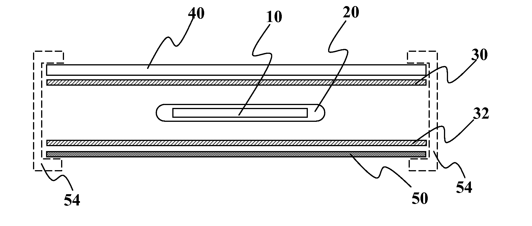
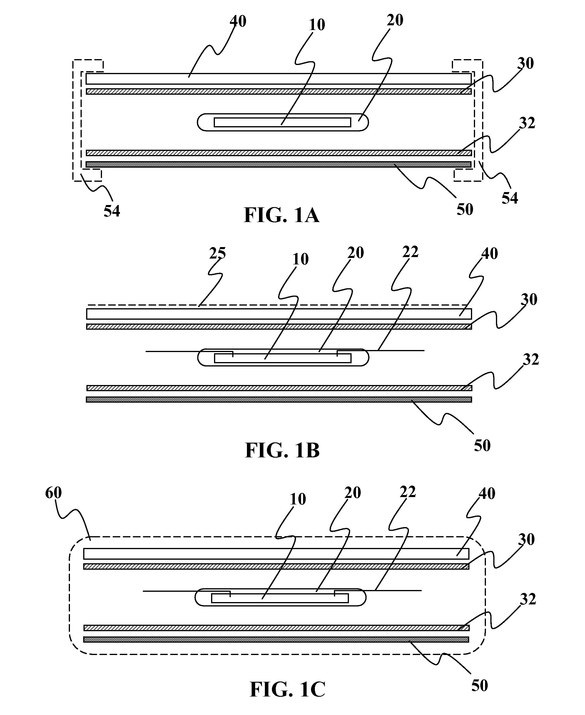
[0009]The present invention provides methods and devices for improved environmental protection for photovoltaic devices and assemblies. In one embodiment, the device comprises of an individually encapsulated solar cell, wherein the encapsulated solar cell includes at least one protective layer coupled to at least one surface of the solar cell. The protective layer has a chemical composition that prevents moisture from entering the solar cell and wherein light passes through the protective layer to reach an absorber layer in the solar cell. It should be understood that the protective layer described herein can be applied to any type of photovoltaic device and is not limited to thin-film, organic, or silicon based solar cells. Individual encapsulation of the cell and / or cell string can effectively address the issue of lateral ingress of vapor between the top and bottom protective sheets.
[0032]In another embodiment of the present invention, a method is provided comprising of providing a plurality of solar cells each having an absorber layer; forming a protective layer covering at least one of the solar cells; placing the solar cells on a module support; and forming a multi-ply module barrier above the solar cells. The protective layer may provide a moisture barrier that prevents moisture damage to the absorber layer. The forming step may comprise of using a substantially organic material. The forming step may comprise of using a substantially inorganic material. The multi-ply module barrier may be comprises of: at least a highly transparent, scratch resistant layer; at least a highly transparent, UV resistant layer; and / or at least a highly transparent, water diffusion barrier layer. The method may include adding at least one adhesion layer to the multi-ply module barrier. The method may also include forming the multi-ply module barrier comprises forming the highly transparent, scratch resistant layer as a top layer.

Problems solved by technology

Unfortunately, this type of outdoor placement also subjects the solar cells and solar cell modules to substantially constant weather and moisture exposure.
A central challenge in finding suitable encapsulating material for use with solar cells is finding one material that has best-in-class qualities for the many properties desired in a good environmental encapsulant.
There may be some materials that provide good moisture barrier qualities but are not sufficiently transparent to pass light down to the absorber layer in the solar cell.
Other layers may be good at moisture and transparent, but discolor over time and reduces transparency with ongoing use.
Although glass provides a very durable and weather resistant layer, it does so at the cost of being expensive, heavy, and rigid.
Glass modules are also generally more challenging to manufacture in a high-throughput manner.
This further complicates the manufacturing process as it is difficult to avoid gaps in the barrier, especially at the interfaces of the edge tape and the glass as well as the edge tape and any bottom layer.
Furthermore, thin-film solar cells are more sensitive to moisture exposure than traditional silicon based solar cells.
It is generally undesirable to expose any type of solar cell to direct moisture contact.

Method used


Image

  • Solar assembly with a multi-ply barrier layer and individually encapsulated solar cells or solar cell strings
  • Solar assembly with a multi-ply barrier layer and individually encapsulated solar cells or solar cell strings
  • Solar assembly with a multi-ply barrier layer and individually encapsulated solar cells or solar cell strings

Examples


Embodiment Construction

[0054]It is to be understood that both the foregoing general description and the following detailed description are exemplary and explanatory only and are not restrictive of the invention, as claimed. It may be noted that, as used in the specification and the appended claims, the singular forms “a”, “an” and “the” include plural referents unless the context clearly dictates otherwise. Thus, for example, reference to “a material” may include mixtures of materials, reference to “a compound” may include multiple compounds, and the like. References cited herein are hereby incorporated by reference in their entirety, except to the extent that they conflict with teachings explicitly set forth in this specification.

[0055]In this specification and in the claims which follow, reference will be made to a number of terms which shall be defined to have the following meanings:

[0056]“Optional” or “optionally” means that the subsequently described circumstance may or may not occur, so that the des...


PUM


Abstract

Methods and devices are provided for improved environmental protection for photovoltaic devices and assemblies. In one embodiment, a photovoltaic device module is provided comprising of a multi-ply module encapsulant, a bottom module layer, and a plurality of solar cells. The multi-ply module encapsulant includes one or more discrete layers comprising of at least a first module layer and at least a second module layer. The plurality of solar cells may be sandwiched between the multi-ply module encapsulant and the bottom module layer. At least one of the cells has a protective layer that provides a level of moisture resistance equal to or higher than any of the layers above the cells. The protective layer is typically above the solar cell and light passes through the multi-ply module encapsulant and the protective layer to reach the solar cell.

Description

CROSS-REFERENCE TO RELATED APPLICATIONS[0001]This patent application claims the benefit of priority to commonly assigned, copending U.S. Provisional Application Ser. No. 60 / 746,626 filed May 5, 2006; commonly assigned, copending U.S. Provisional Application Ser. No. 60 / 746,961 filed May 10, 2006; commonly assigned, copending U.S. Provisional Application Ser. No. 60 / 804,570 filed Jun. 12, 2006; commonly assigned, copending U.S. Provisional Application Ser. No. 60 / 804,571 filed Jun. 12, 2006; and commonly assigned, copending U.S. Provisional Application Ser. No. 60 / 806,096 filed Jun. 28, 2006. All of the foregoing applications are fully incorporated herein by reference for all purposes.FIELD OF THE INVENTION[0002]This invention relates generally to solar cells, and more specifically, to protective layers used to protect solar cells, solar cell strings, and / or solar cell modules against environmental exposure damage.BACKGROUND OF THE INVENTION[0003]Solar cells and solar modules convert...

Claims


Application Information

Patent Timeline
Patent Type & Authority Applications(United States)
IPC IPC(8): H02N6/00
CPCH01L27/301H01L31/0392H01L31/048H02S20/23Y02B10/12Y02E10/549H01L51/448H01L31/03925H01L31/03928Y02E10/541Y02B10/10H10K39/10H10K30/88
Inventor ADRIANI, PAULCAPPS, PHILIPSHEATS, JAMES R.
Owner NANOSOLAR
Learn More