Boundary Layer Wind Turbine

a wind turbine and boundary layer technology, applied in the direction of propellers, propulsive elements, water-acting propulsive elements, etc., can solve the problems of obscuring the landscape, needing an even horizontal air inflow, and affecting the safety of birds and air traffic, so as to achieve reliable and effective means, increase rotational velocity, and increase torque

Inactive Publication Date: 2007-12-27
NICA HORIA
View PDF22 Cites 43 Cited by
  • Summary
  • Abstract
  • Description
  • Claims
  • Application Information

AI Technical Summary

Benefits of technology

[0019] Preferably, a wind turbine according to the present invention is able to operate in very broad wind conditions, such as velocities up to 130 mph, and frequently changing wind directions. The device provides a reliable and effective means for directing air currents into the rotor assembly, which is attached directly to a vertical shaft.
[0020] In general terms, the invention involves various embodiments of a vertical-axis wind turbine. Preferably, the stator blades are designed with an inward sinuous shape curvature and an outward simple curvature. The stator blades are disposed around the rotor as such that, regardless of the wind direction, the air inflow will be redirected tangentially to the rotor to impart a higher rotational velocity and greater torque upon the turbine shaft. In a preferred embodiment, the upper top surface and lower bottom surface of the stator assembly is designed as hemispheres for maximum air inflow. The significant size difference between the inflow and the outflow openings of the air channels created by the stator blades create a natural compression and a substantial air speed increase that achieve higher efficiency even in low wind. The disposition of the stator blades also prevents the disruption of rotation by shielding the rotors from winds counter-directional to their rotation which may occur as the wind shifts. The turbine may be equipped with any number of stator blades, however a preferred embodiment has between six and twelve stator blades.
[0021] The vertical rotor assembly, in a preferred embodiment, consists of a series of modified Tesla disks each of them having a plurality of small curved blades disposed circumferentially on the disk and continued with small ribs helically disposed on the upper surface of the disk. Between two ribs on the upper surface there is a corresponding rib on the lower surface of the disk to extract the airflow energy through drag and viscous effect having as a result a high-efficient VAWT. The turbine may be equipped with any number of disks, however a preferred embodiment has at least 50 disks.

Problems solved by technology

Horizontal axis windmills have been used extensively to drive electrical generators, however they suffer from several disadvantages, including the need for an even horizontal air inflow, danger to birds and air traffic, obscuring the landscape with banks of rotating windmills, and in the case of large diameter horizontal axis propellers, supersonic speeds at the tips of the rotors.
Compared to VAWT where its exposure remains constant regardless of the wind direction, the horizontal axis windmill must turn to face the wind direction, which is considered as a disadvantage as there are additional moving parts involved in the construction.
One of the major drawbacks of that design is the fact that the air intake module needs to face the wind, so it requires a yaw mechanism to orient it into the wind.
The numerous and drastic changes in airflow directions entail a power loss in the airflow and a reduction of the turbine efficiency, as the energy of the wind is transformed into rotation of the turbine only at the last airflow direction change.
A disadvantage of all the horizontal and vertical axis windmills of the prior art relates to their inability to use remaining energy left in the airflow after hitting the windmill blades.
Unfortunately, in most cases the prior art enables the capture of only a fraction, the first impulse, of the wind power.
Unfortunately this previous art is not suited to capture wind energy for several reasons such as the air viscosity is too low, the normal wind speed is too low and the whole design with a casing enclosure and only one access opening is impractical for wind turbines.

Method used


Image

  • Boundary Layer Wind Turbine
  • Boundary Layer Wind Turbine
  • Boundary Layer Wind Turbine

Examples


Embodiment Construction

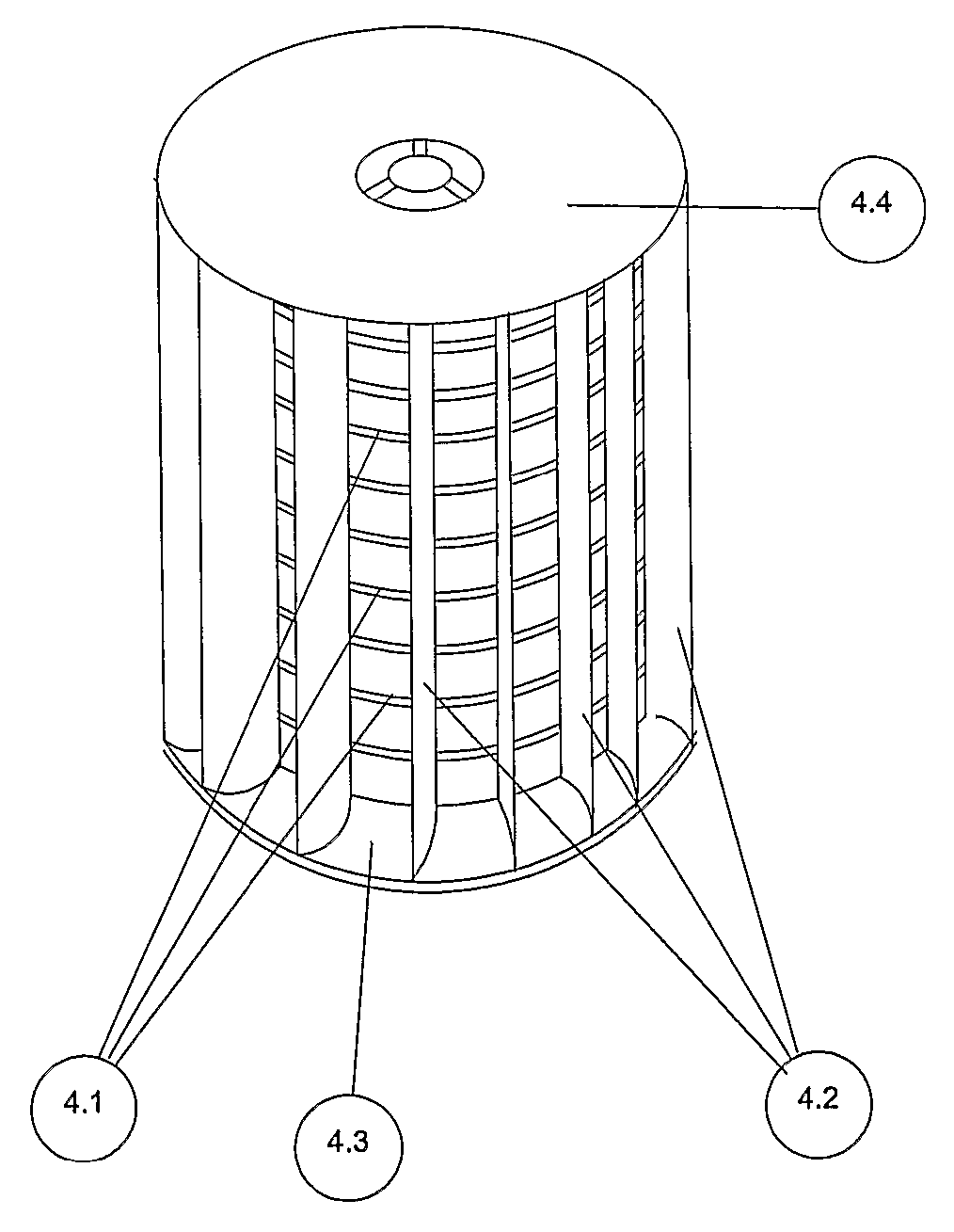
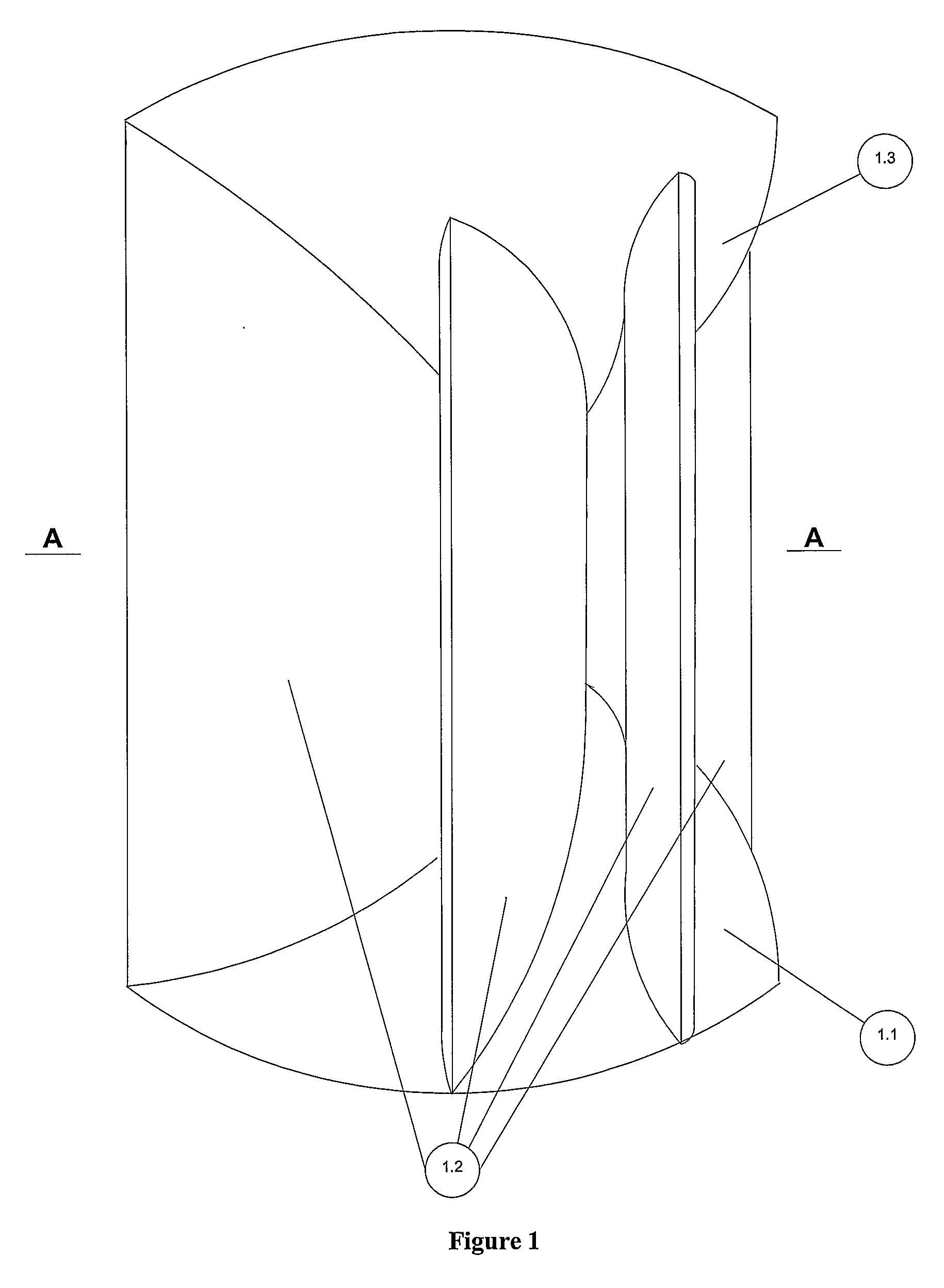
[0035]FIG. 1 shows a vertical axis wind turbine as seen from exterior, where only the stator blades (1.2) are visible, according to a preferred embodiment of the present invention. The upper surface (1.1) and the lower surface (1.3) are shaped as hemispheres to create a maximum air inflow. These surfaces (1.1, 1.3) may alternatively be truncated cones or elliptical surfaces.

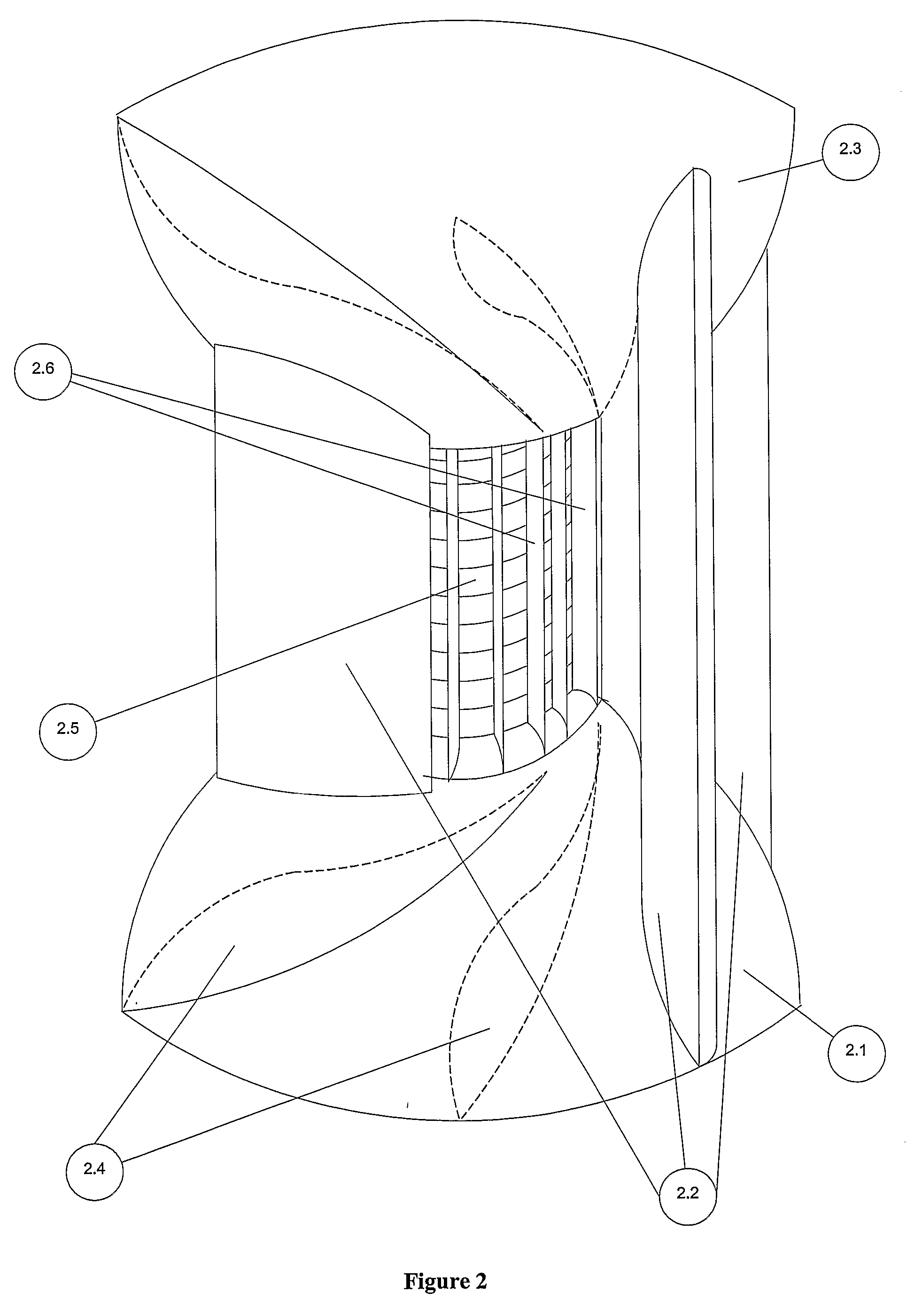
[0036]FIG. 2 shows the vertical axis wind turbine where two stator blades (2.4) were removed to make the rotor (2.5) visible. The presented stator blades orientation is counter clockwise. It will be understood of course that the orientation of the stator blades (2.2) and rotor blades (2.6) may be reversed to drive the turbine in a clockwise direction if desired.

[0037]FIG. 3 is a horizontal sectional view on the line A-A of FIG. 1, showing the disposition of stator blades (3.2) on the hemisphere lower surface (3.1) and around the rotor (3.3) as such that, regardless of the wind direction, the air inflow will be ...


PUM


Abstract

A wind turbine including a stator assembly having a plurality of stator blades for tangentially redirecting wind into a rotor assembly having a plurality of vertical rotor blades disposed circumferentially on a plurality of disks stacked one on top of each other. Each disk defines at least one opening thereon for redirecting the wind axially through each of the disks.

Description

FIELD OF THE INVENTION [0001] The present invention relates to wind turbines used to convert wind energy into mechanical energy, more specifically to vertical-axis turbines with stator devices that channel the air flow into a central rotor. The present invention design is based on the Coanda effect in fluids which translates into a more efficient vertical-axis turbine. BACKGROUND OF THE INVENTION [0002] Wind as a source of energy is a concept that has been promoted from ancient time. According to historical sources, there is evidence which shows that windmills were in use in Babylon and in China as early as 2000 B.C. [0003] Wind is used as a source of energy for driving horizontal axis and vertical axis windmills. Horizontal axis windmills have been used extensively to drive electrical generators, however they suffer from several disadvantages, including the need for an even horizontal air inflow, danger to birds and air traffic, obscuring the landscape with banks of rotating windmi...

Claims


Application Information

Patent Timeline
Patent Type & Authority Applications(United States)
IPC IPC(8): F03D3/00F03D9/25
CPCF03D3/0409F03D3/0427Y02E10/74F03D3/062F05B2240/211F03D3/061
Inventor NICA, HORIA
Owner NICA HORIA
Why Eureka
Try Eureka