Control method for motor and controller for motor

a technology of control method and controller, which is applied in the direction of dynamo-electric converter control, dynamo-electric gear control, electric generator control, etc., can solve the problems of inability to disclose specific means and inaccurate detection of current, and achieve high reliability, simple structure, and high performance.

Inactive Publication Date: 2007-12-27
NSK LTD
View PDF13 Cites 29 Cited by
  • Summary
  • Abstract
  • Description
  • Claims
  • Application Information

AI Technical Summary

Benefits of technology

[0027]According to control method and the controller for the motor according of the present invention, since the level of a voltage command value is restricted so that the current of at least (N−1) phases can be detected. The current of a phase that cannot be detected is estimated in accordance with prescribed expressions by using the current detected value of other phase and a control is continuously carried out by using the estimated current value, a motor control of high performance and high reliability can be realized.
[0028]Further, since the current is detected based on a current detecting resistance connected to the lower stage of a bridge circuit, a structure is simple and a cost is not increased. When the control method and the controller for the motor according to the present invention are applied to the electric power steering, even if one current detecting system generates the failure, the abnormality or the undetectable state, a steering operation can be continuously controlled. Thus, the electric power steering device of high reliability and high performance can be provided.
[0029]The present invention relates to a control method and a controller for a motor of N (an integer of 2 or more) phases and more particularly to a control method and a controller for an electric power steering device in which the levels of voltage command values of phases are respectively restricted so as to detect the current of at least (N−1) phases for a control system for controlling the motor of the N phases, and when a failure or an abnormality (hereinafter simply referred to as “failure”) of a current detecting system is generated, the current of a phase that cannot be detected due to the failure is estimated from the current value of other phase in accordance with a prescribed expressions to continuously control the motor. Therefore, even when the current detecting system of one phase is failed or brought to an undetectable state, the control of the motor can be continuously carried out by a normal operation so that a control of high reliability and high performance can be realized.

Problems solved by technology

However, when the duty ratio of the FET 4 to the FET 6 of the lower stage is not higher than a prescribed value, there is a problem that the current cannot be accurately detected.
However, there are not disclosed any specific examples in which it is decided whether or not the current of other phase is accurately detected and how the current value of the phase in which the current cannot be accurately detected is calculated.
Further, specific means is not disclosed when a current detected value is not precise due to a failure.

Method used


Image

  • Control method for motor and controller for motor
  • Control method for motor and controller for motor
  • Control method for motor and controller for motor

Examples


Embodiment Construction

[0044]Now, an embodiment of the present invention will be described below with reference to the drawings.

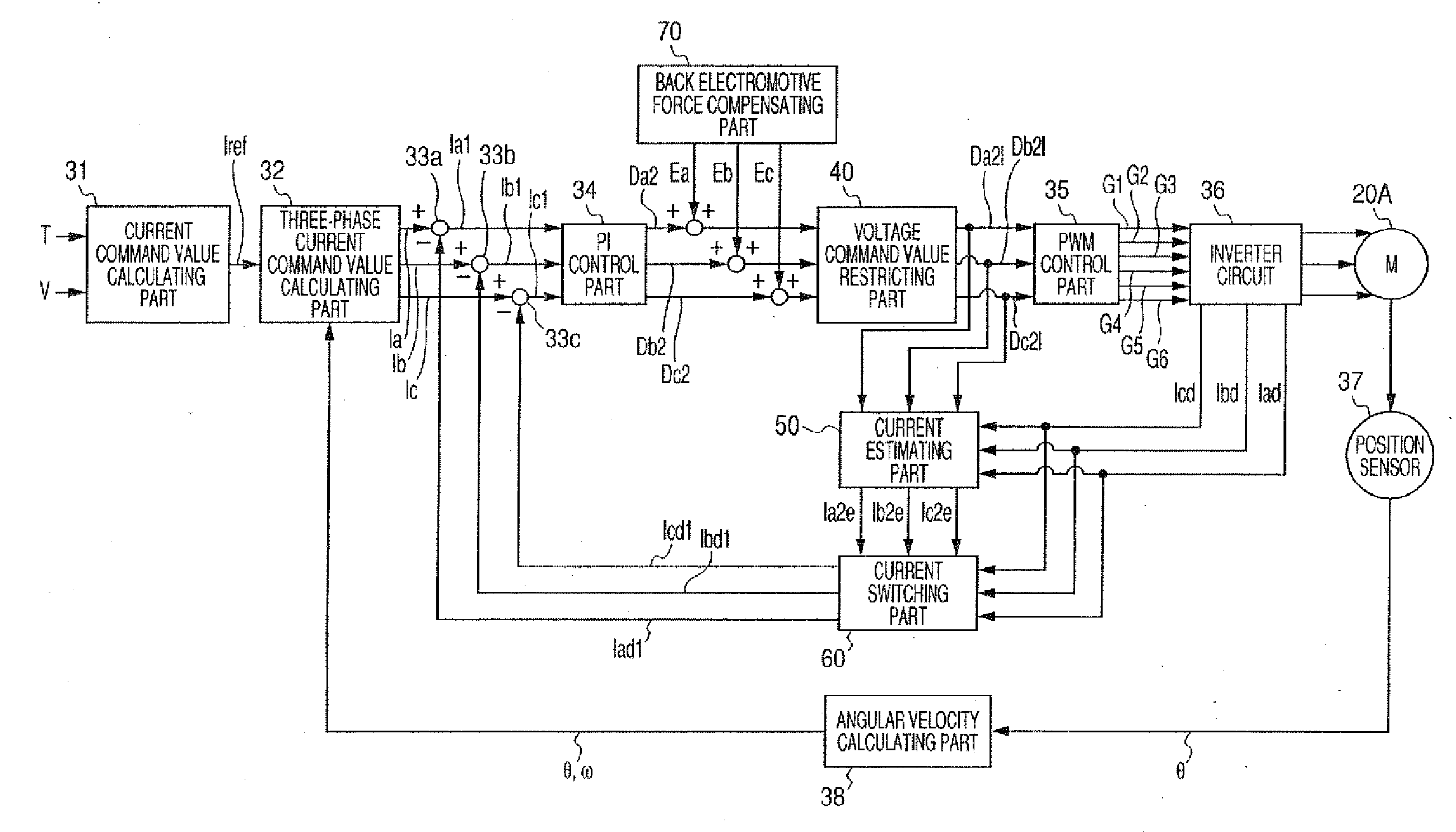
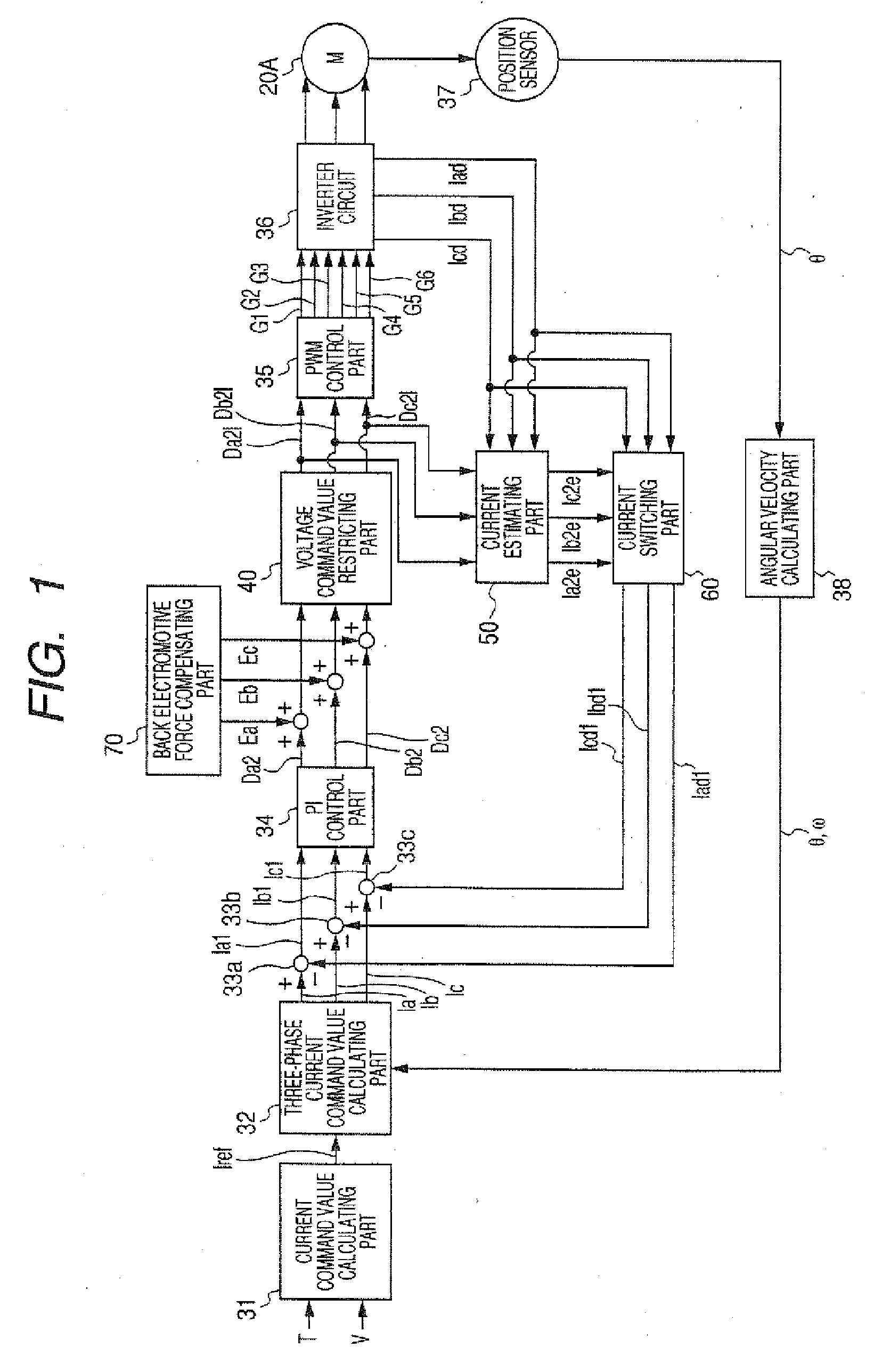
[0045]FIG. 1 shows the structure of one embodiment of the present invention so as to correspond to that of FIG. 12. A voltage command value restricting part 40, a current estimating part 50, a current switching part 60 and a back electromotive force compensating part 70 are newly provided. Specifically, voltage command values Da2, Db2 and Dc2 of three phases from a PI control part 34 are added to voltage compensated values Ea, Eb and Ec from the back electromotive force compensating part 70 and inputted to the voltage command value restricting part 40. The voltage command values Da21, Db21 and Dc21 restricted in the voltage command value restricting part 40 are inputted to a PWM control part 35 and inputted to the current estimating part 50 for estimating the current value of the motor of the current detecting system that is failed or brought to the undetectable state. Current es...


PUM


Abstract

This invention provides a control method for a motor that calculates a voltage command value based on a difference between a current command value and a current detected value and controls a PWM based on the voltage command value.The control method includes steps of: detecting a failure or an undetectable state of a current detecting system; obtaining a current estimated value of a failure phase or an undetectable state phase by using the current detected value except the failure phase or the undetectable state phase when the failure or the undetectable state is detected; and continuously controlling the motor by using the current estimated value.

Description

[0001]This application is based on and claims the benefit of priority from the prior Japanese Patent Application No. 2006-161297, filed on Jun. 9, 2006, the entire content of which is hereby incorporated by reference.BACKGROUND OF THE INVENTION[0002]1. Technical Field[0003]The present invention relates to a control method and a controller for a motor, and more particularly to a control method and a controller for a motor with high reliability that can continuously control a motor when a failure or an abnormality is generated in one current detecting system and are most suitably applied to a control of an electric power steering.[0004]2. Background Art[0005]As a control for a motor, for instance, there is an electric power steering device in which a steering device for a vehicle is driven by controlling the motor torque as a steering assist force. In the electric power steering device, the driving force of the motor is applied on a steering shaft or a rack shaft as the steering assis...

Claims


Application Information

Patent Timeline
Patent Type & Authority Applications(United States)
IPC IPC(8): H02P27/04B62D5/04B62D6/00B62D119/00H02P21/14H02P21/18H02P21/22H02P21/24H02P23/12H02P23/14H02P27/06H02P27/08
CPCH02P29/022H02P6/08H02P29/032H02P23/14
Inventor SAKAGUCHI, TORUENDO, SHUJIKOVUDHIKULRUNGSRI, LILIT
Owner NSK LTD
Why Eureka
Try Eureka