Exhaustive diagnosis of bridging defects in an integrated circuit

a technology of integrated circuit and bridging defect, applied in the field of exhaustive diagnosis of bridging defect in integrated circuit, can solve the problems of ic with undetected bridge, bridging defect, escaping detection, etc., and achieve the effect of saving system resources in computation

Inactive Publication Date: 2007-12-27
GLOBALFOUNDRIES INC
View PDF13 Cites 4 Cited by
  • Summary
  • Abstract
  • Description
  • Claims
  • Application Information

AI Technical Summary

Benefits of technology

[0011]A method, system and computer program product for diagnosing a bridging defect in an integrated circuit including multiple nodes are disclosed. Quiescent power supply current (IDDQ) of the integrated circuit (IC) is measured under multiple test vectors. Logic states of the nodes on the IC are also obtained under the multiple test vectors. The nodes are partitioned into sets based on their logic states under low-current test vectors. Large sets are further divided into subsets (“state-count subsets”) based on the logic states of nodes under high-current test vectors. For large sets, explicit evaluation under the IDDQ bridge fault model is performed only on pairs of nodes belonging to subsets having complementary state counts, to save system resources in computation. Exhaustive diagnosis considering all pairs of nodes on the IC is thus feasibly achieved due to the saving of system resources.

Problems solved by technology

Bridging defects, especially high-resistance bridges, may also escape detection during manufacturing test.
An IC with an undetected bridge may thus erroneously be shipped to a customer, where it may fail immediately or after an extended period of use.
This tolerance can lead to less precise diagnosis or to diagnosis of the wrong defect.
A fundamental issue for diagnostic methods using the IDDQ bridge fault model is the set of candidate bridging faults considered during a diagnosis.
Thus, the consideration of only realistic bridges significantly reduces the CPU resources required for diagnosis.
Unfortunately, at least two factors limit the applicability of any diagnostic method that relies on a set of realistic bridges.
First is the expense of extracting and storing the realistic bridges.
Layout extraction is typically expensive in terms of CPU resources.
However, a more significant disadvantage of limiting diagnosis to a set of realistic faults is that the rules used during layout extraction to determine which bridges are “realistic” are based on assumptions that may not always be valid.
In general, the capacity of a semiconductor manufacturing line to produce bridging defects that are “unexpected” is significant.
Chakravarty and Suresh rely on an implicit representation of all possible two-node bridges using a “set of ordered pairs of sets (SOPS).” The amount of memory required for this method, however, can increase exponentially and potentially exceed the capacity of a computer as each test vector is considered and each SOPS is subdivided.
In addition, results for the Chakravarty and Suresh method were published only for a set of small benchmark circuits, and even these results include a test case that requires almost an hour of CPU time.
The application of the Chakravarty and Suresh method is thus not a feasible alternative for even moderately-sized industrial circuits, whose sizes exceed that of the benchmark circuits by 100 times or more.
The present state of the art technology does not provide a satisfactory solution to this need.

Method used


Image

  • Exhaustive diagnosis of bridging defects in an integrated circuit
  • Exhaustive diagnosis of bridging defects in an integrated circuit
  • Exhaustive diagnosis of bridging defects in an integrated circuit

Examples


Embodiment Construction

[0027]The following detailed description of embodiments refers to the accompanying drawings, which illustrate specific embodiments of the invention. Other embodiments having different structures and operations do not depart from the scope of the present invention.

1. System Overview

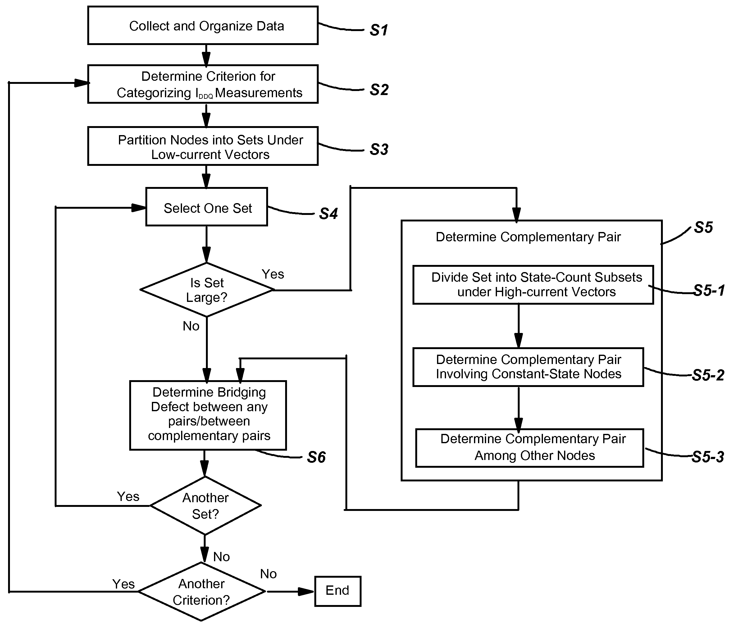
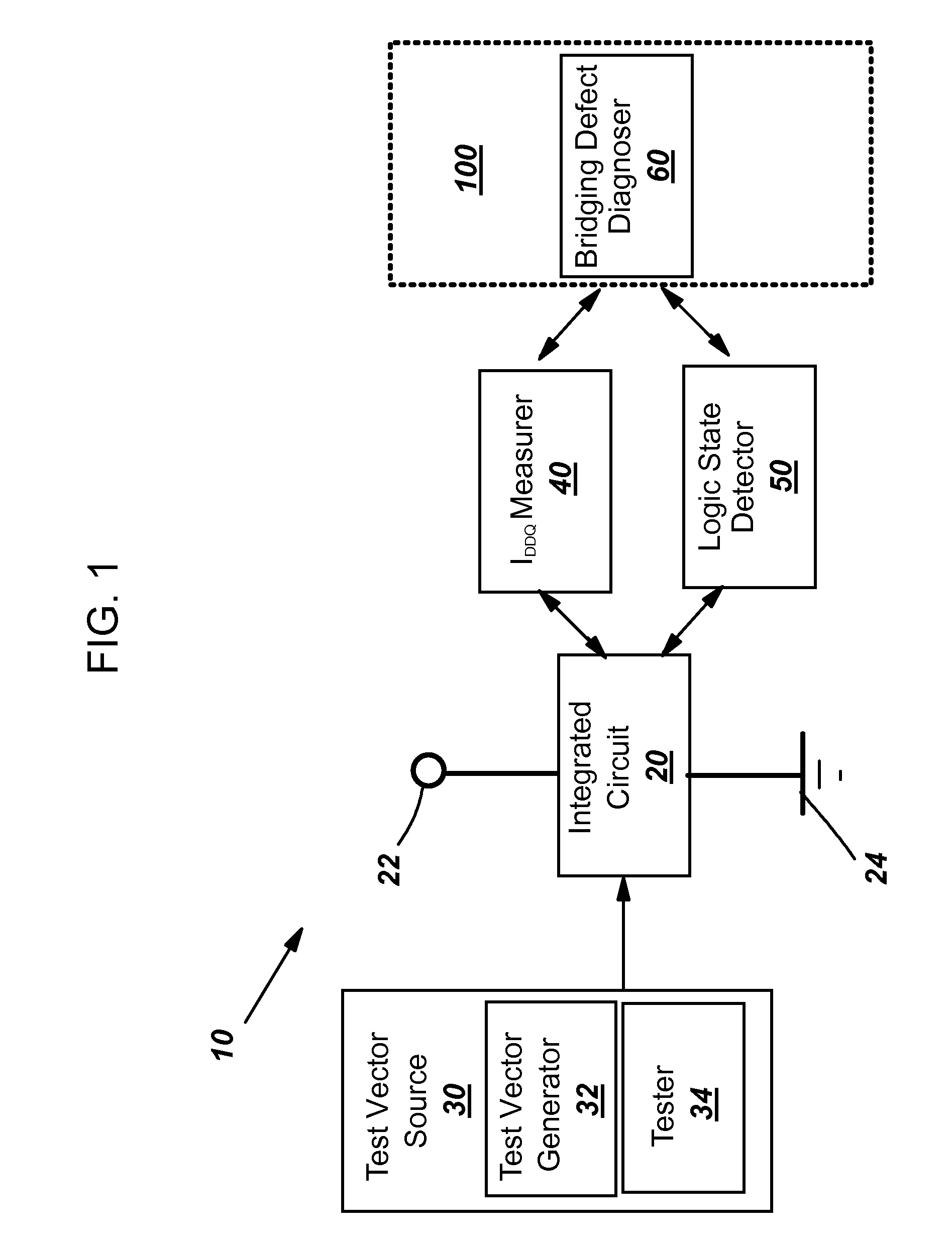
[0028]Referring to FIG. 1, a schematic view of an illustrative bridging defect diagnosis system (diagnosis system) 10 is shown. According to one embodiment, diagnosis system 10 includes an integrated circuit (IC) 20 that includes multiple nodes as should be appreciated; a test vector source 30 including a test vector generator 32 and a tester 34; an IDDQ measurer 40; a logic state detector 50; and a bridging defect diagnoser 60. Integrated circuit (IC) 20 may be coupled between a positive power supply (VDD) 22 and a ground 24. In operation, test vector generator 32 generates test vectors and tester 34 inputs the generated test vectors into IC 20, which drives / sets the nodes on IC 20 to different logic stat...


PUM


Abstract

A method, system and computer program product for diagnosing a bridging defect in an integrated circuit including multiple nodes are disclosed. Quiescent power supply current (IDDQ) of the integrated circuit (IC) is measured under multiple test vectors. Logic states of the nodes on the IC are also obtained under the multiple test vectors. The nodes are partitioned into sets based on their logic states under low-current test vectors. Large sets are further divided into subsets (“state-count subsets”) based on the logic states of nodes under high-current test vectors. For large sets, explicit evaluation under the IDDQ bridge fault model is performed only on pairs of nodes belonging to subsets having complementary state counts, to save system resources in computation. Exhaustive diagnosis considering all pairs of nodes on the IC is thus feasibly achieved due to the saving of system resources.

Description

FIELD OF THE INVENTION[0001]The invention relates generally to diagnosing faults in an integrated circuit, and more particularly to diagnosing a bridging defect in an integrated circuit.BACKGROUND OF THE INVENTION[0002]The logical and electrical behavior of a bridging defect, an unintended electrical connection or “short” between nodes in an integrated circuit (IC) design, has long been a subject of research within the test community. Bridging defects are a prime cause of IC manufacturing yield loss, and reducing their number thus has significant financial benefit for an IC manufacturer. Bridging defects, especially high-resistance bridges, may also escape detection during manufacturing test. An IC with an undetected bridge may thus erroneously be shipped to a customer, where it may fail immediately or after an extended period of use.[0003]In no field is the ability to anticipate and accommodate the varied behaviors of bridging defects more central to success than in fault diagnosis...

Claims


Application Information

Patent Timeline
Patent Type & Authority Applications(United States)
IPC IPC(8): G01R31/26
CPCG01R31/3008G01R31/2853
Inventor HEABERLIN, DOUGLAS C.
Owner GLOBALFOUNDRIES INC
Why Eureka
Try Eureka