dB-linear analog variable gain amplifier (VGA) realization system and method

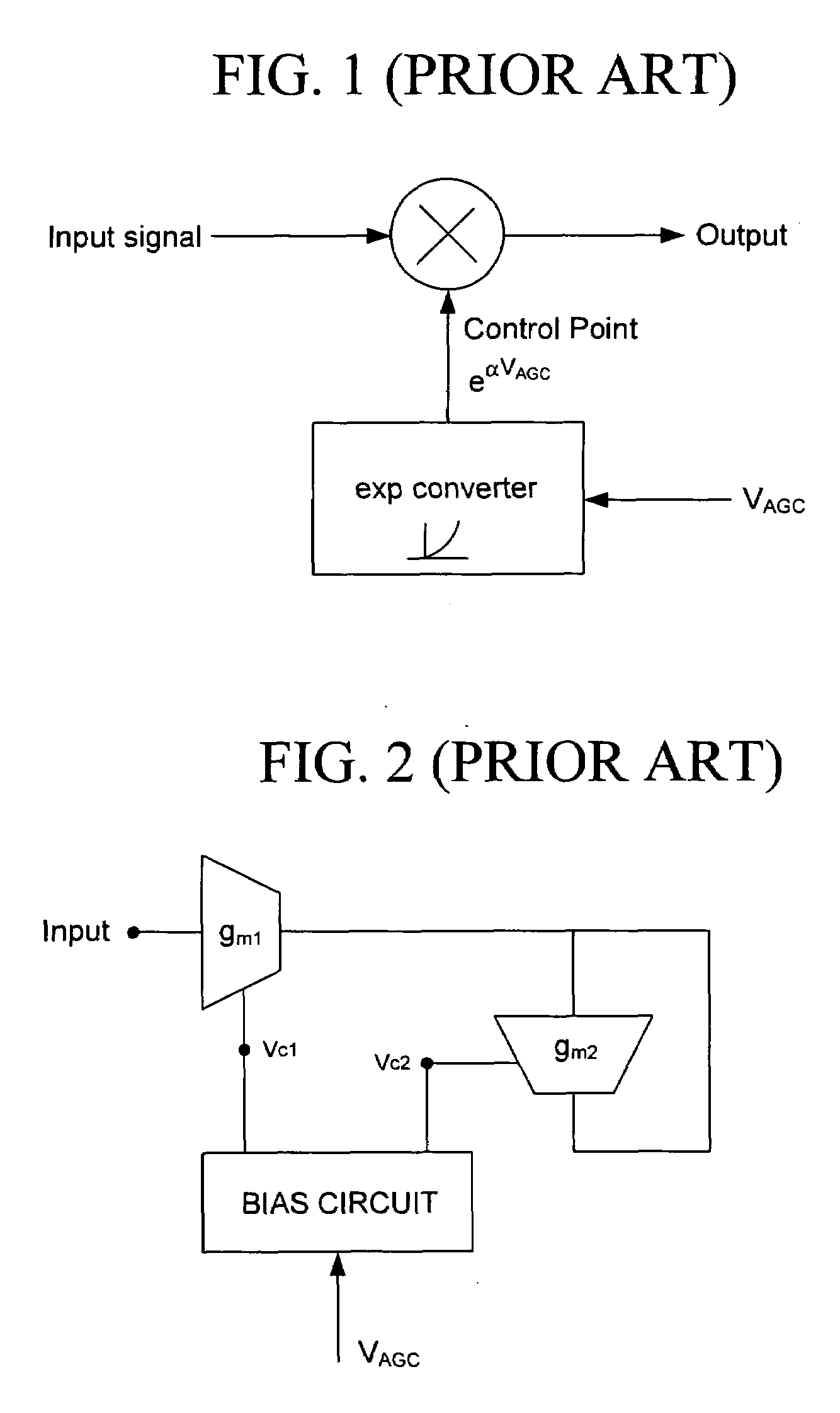
a gain amplifier and linear analog technology, applied in the direction of gain control, volume compression/expansion having semiconductor devices, analog signal digital control, etc., can solve the problems of limited signal headroom, difficulty in realizing multipliers or tunable gm stages, and general problems of methods of fig. 1 and 2

Active Publication Date: 2007-12-27
ATMEL CORP
View PDF4 Cites 24 Cited by
  • Summary
  • Abstract
  • Description
  • Claims
  • Application Information

AI Technical Summary

Problems solved by technology

Unfortunately, the methods of FIGS. 1 and 2 generally suffer from, first, limited signal headroom.
This is mainly caused by the difficulty of realizing multipliers or tunable gm stages with rail-to-rail swing.
Second, the methods of FIGS. 1 and 2 tend to suffer from noise performance.
The noise and non-ideality of those devices generally leads to poor noise performance (as compared to op-amp based circuits).
Third, the methods of FIGS. 1 and 2 tend to suffer from limited VGA linearity.
Such techniques are sensitive to device non-idealities as well component mismatches.
Generally, this results in signal distortion that limits the overall dynamic range of the VGA.
Fourth, the methods of FIGS. 1 and 2 tend to suffer from VGA gain mismatches.
Hence, in applications where the use of matched VGAs is required, VGA circuits realized using these conventional methods will generally be harder to use (statistically, a larger percentage of components will exhibit non-acceptable mismatches).
Hence, the VGA typically cannot drive a load resistance directly.
In conclusion, the conventional methods, as illustrated in FIGS. 1 and 2, offer clear disadvantages relating to: (1) limited signal swing; (2) higher noise that limits the minimum signal that the VGA circuits can process; (3) degraded over-all linearity that results in signal distortion, especially at higher signal levels; (4) difficulty in achieving sufficiently good matching between similar VGA circuits; and (5) in most cases, the outputs of the transconductor as well as the multiplier is un-buffered.
Hence, the VGA cannot drive a load resistance directly, whereby an extra buffer stage is necessary to achieve this.

Method used


Image

  • dB-linear analog variable gain amplifier (VGA) realization system and method
  • dB-linear analog variable gain amplifier (VGA) realization system and method
  • dB-linear analog variable gain amplifier (VGA) realization system and method

Examples


Embodiment Construction

[0035]The embodiments herein and the various features and advantageous details thereof are explained more fully with reference to the non-limiting embodiments that are illustrated in the accompanying drawings and detailed in the following description. Descriptions of well-known components and processing techniques are omitted so as to not unnecessarily obscure the embodiments herein. The examples used herein are intended merely to facilitate an understanding of ways in which the embodiments herein may be practiced and to further enable those of skill in the art to practice the embodiments herein. Accordingly, the examples should not be construed as limiting the scope of the embodiments herein.

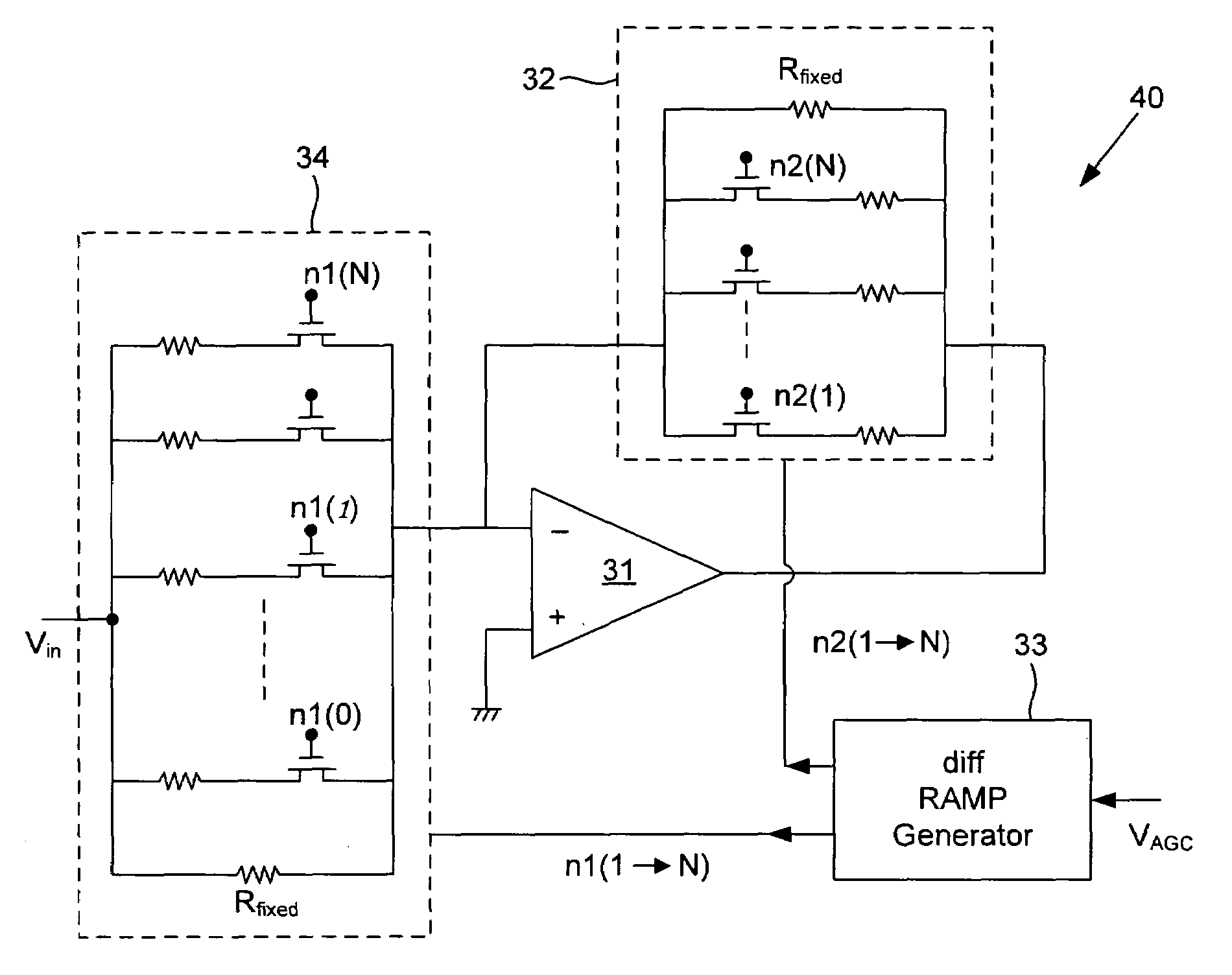
[0036]As mentioned, there remains a need for a new technique for realizing dB-linear VGAs. The embodiments herein achieve this by providing a system and method for dB-linear analog VGA realization with rail-to-rail input and output swings, low noise, and high linearity. Referring now to the dra...


PUM


Abstract

A dB-linear variable gain amplifier, a method for creation, and a system includes an amplifier; a pair of resistor arrays operatively connected to the amplifier, wherein each resistor array comprises MOS transistor resistive switches; a differential ramp-generator circuit operatively connected to the pair of resistor arrays; and voltage control lines generated by the differential ramp-generator circuit, wherein the voltage control lines are operatively connected to each of the MOS transistor resistive switches in the pair of resistor arrays. The number of the voltage control lines that are operatively connected to the each of the MOS transistor resistive switches is equal to the number of resistors in a particular resistor array. The differential ramp-generator circuit is preferably operable to take an automatic gain control voltage and generate a series of differential ramp voltages and apply the series of differential ramp voltages to one of the MOS transistor resistive switches.

Description

BACKGROUND[0001]1. Technical Field[0002]The embodiments herein generally relate to electrical circuits, and, more particularly, to techniques for implementing an analog variable gain amplifier (VGA) to enhance overall system signal processing.[0003]2. Description of the Related Art[0004]To realize a dB-linear VGA circuit in a non-bipolar junction transistor (BJT) technology, the exponential automatic gain control (AGC) characteristics is approximated by Equation (1): ex=(1+x) / (1−x). One method to realize the VGA is shown in FIG. 1. The AGC control voltage is applied to an exponential converter circuit that converts the AGC control voltage according to the previous expression (or other approximations). The output voltage of this circuit is then fed into a control port of a multiplier. The signal is then applied to the input port of the multiplier circuit. The multiplier circuit will linearly multiply the input signal with the signal applied to the control port. Hence, the dB-Linear V...

Claims


Application Information

Patent Timeline
Patent Type & Authority Applications(United States)
IPC IPC(8): H03G3/20
CPCH03G1/0088H03G7/06H03G3/3047H03G3/001
Inventor ELWAN, HASSANFAHIM, AMRISMAIL, ALYYOUSSOUFIAN, EDWARD
Owner ATMEL CORP
Why Eureka
Try Eureka