Image sensing apparatus having electronic zoom function, and control method therefor

a technology of image sensing apparatus and electronic zoom, which is applied in the direction of exposure control, printing, instruments, etc., can solve the problems of increasing overall power consumption and the inability to display an image smoothly, and achieve the effect of smoother display or recording of images

Active Publication Date: 2007-12-27
CANON KK
View PDF5 Cites 25 Cited by
  • Summary
  • Abstract
  • Description
  • Claims
  • Application Information

AI Technical Summary

Benefits of technology

[0013]The present invention has been made in consideration of the above situation, and has as its object to be able to carry out smoother display or recording of images when executing an EVF function and recording moving images while changing the angle of view with an electronic zoom.

Problems solved by technology

As a result, overall power consumption also increases.
In addition, an image sensing apparatus using an image sensing element employing the X-Y address type scanning method of Japanese Patent Laid-Open (JPA) 2002-314868 has the following problem: Specifically, combination of using electronic zoom that changes the image sensing element read drive method at each predetermined zoom ratio and electronic zoom that enlarges the image data obtained from the image sensing element in accordance with designated zoom ratio makes it impossible to display an image smoothly when the image sensing element read drive method is changed.

Method used


Image

  • Image sensing apparatus having electronic zoom function, and control method therefor
  • Image sensing apparatus having electronic zoom function, and control method therefor
  • Image sensing apparatus having electronic zoom function, and control method therefor

Examples


first embodiment

[0035]Image Sensing System Configuration

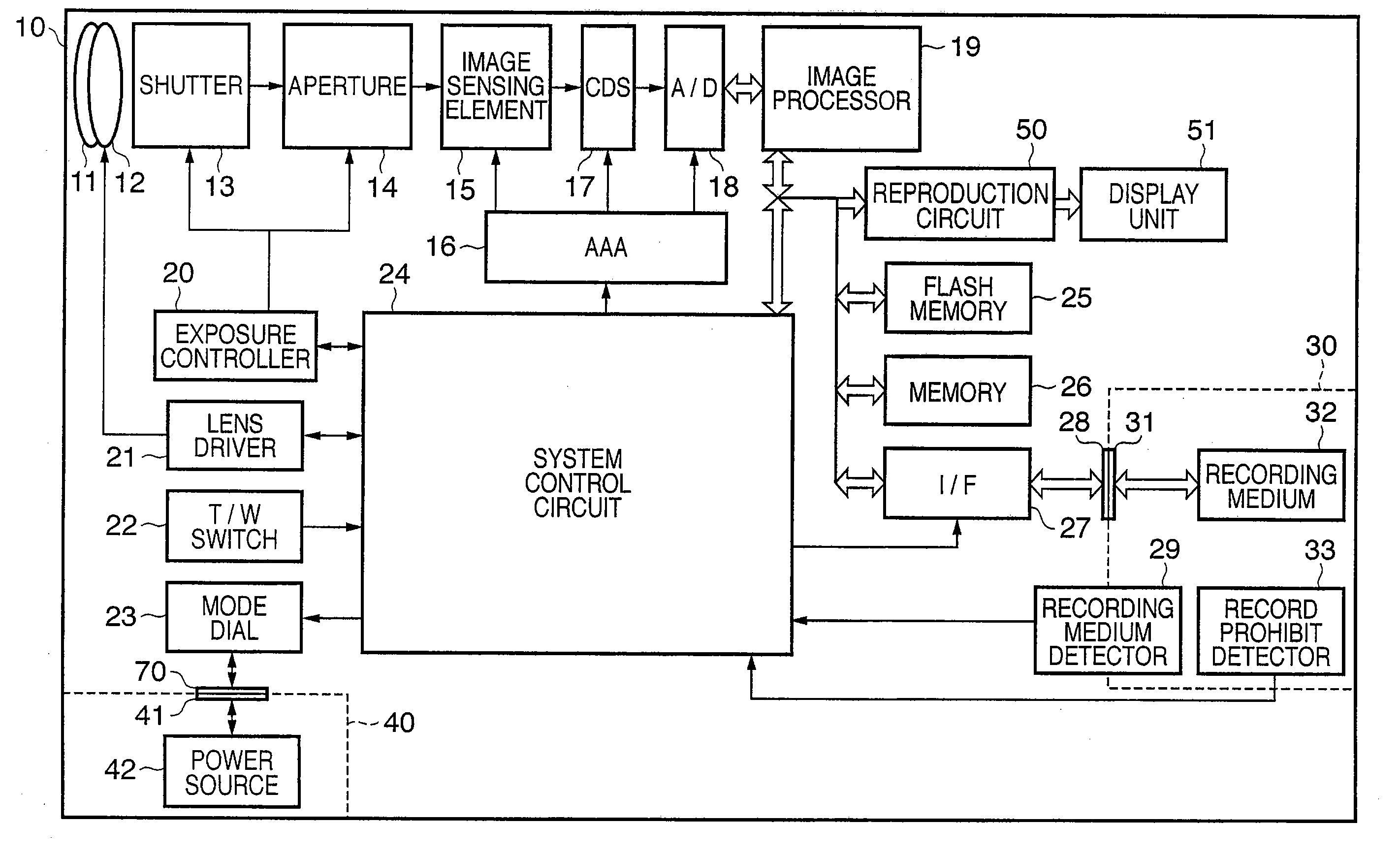
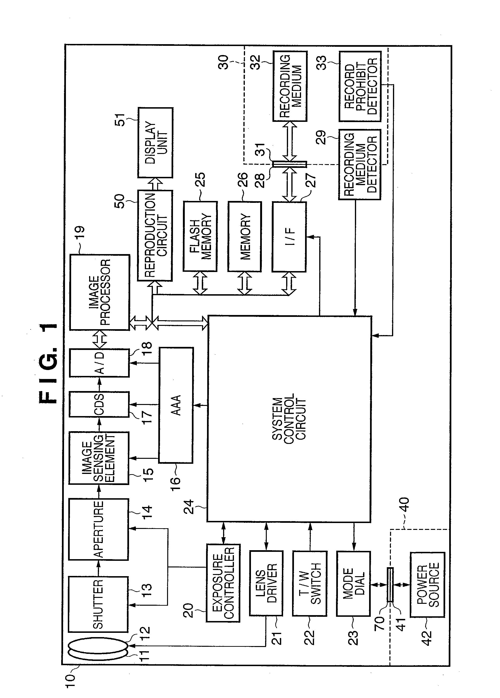
[0036]FIG. 1 is a block diagram showing the configuration of an image sensing system according to an embodiment of the present invention. In FIG. 1, reference numeral 10 denotes an image sensing apparatus. In the image sensing apparatus 10, reference numeral 11 denotes a zoom lens, 12 denotes a focus lens, 13 denotes a mechanical shutter that shuts out light to a later stage, and 14 denotes an aperture that adjusts the amount of light reaching the later stage. Reference numeral 15 denotes an image sensing element and 16 denotes a timing pulse generator that generates a timing pulse needed for image sensing element 15 driving and sampling that is driven by a system control circuit 24. Reference numeral 17 denotes a CDS element that performs correlated double sampling (CDS) on the output of the image sensing element 15 based on the timing pulse generated by the timing pulse generator 16, and 18 denotes an A / D converter that quantizes the CDS out...

second embodiment

[0106]Next, a description is given of a second embodiment of the present invention.

[0107]The system configuration as well as the configuration and form of control of the image sensing element in the second embodiment are the same as those of the first embodiment, and therefore a description thereof is omitted. The second embodiment adds to the first embodiment a concentration on the viewing of the EVF image displayed on the display unit.

[0108]In the case of the first embodiment described above, with both electronic zoom control in the image quality priority mode and electronic zoom control in the speed priority mode, when the drive of the image sensing element 15 is switched a large difference occurs in perceived resolution of the EVF images displayed on the display unit before and after the switch. This phenomenon occurs because the amount of information involved differs depending on the size of the area of the image obtained from the image sensing element 15 that is used for the i...


PUM


Abstract

In an image sensing apparatus having an image sensing element that senses an object and outputs image data and an electronic zoom function, either a first processing mode or a second processing mode is set and an angle of view is designated. In the first processing mode, the image sensing element is driven by switching reading regions and reading methods of image data from the image sensing element based on the designated angle of view and the image data is read, processed, and the angle of view determined by the switched reading region is changed to the designated angle of view. In the second processing mode, the reading region and the reading method of the image data are fixed and the image data output from the image sensing element is processed, and the angle of view determined by the fixed reading region changed to the designated angle of view.

Description

BACKGROUND OF THE INVENTION[0001]1. Field of the Invention[0002]The present invention relates to an image sensing apparatus that senses still images and moving images and a control method therefore, and more particularly, to an image sensing apparatus having an electronic zoom function, and a control method therefor.[0003]2. Description of the Related Art[0004]Image sensing apparatuses, notably digital cameras and digital video cameras, that form an optical image on an image sensing element, perform various signal processes on the image data obtained by photoelectric conversion, and output a visual image of the object field on a liquid crystal monitor, and at the same time record on a recording medium, have been proposed. The recorded image data is either a still image, which uses substantially all of the data of pixels located within the effective area of the image sensing element, or a moving image, which uses only data obtained by thinning and / or averaging the data of pixels loca...

Claims


Application Information

Patent Timeline
Patent Type & Authority Applications(United States)
IPC IPC(8): H04N5/262G03B5/00G03B7/00G03B17/16H04N5/228H04N5/335H04N5/345H04N5/374
CPCH04N3/155H04N5/232H04N5/3454H04N5/23296H04N5/2628H04N5/23245H04N23/667H04N23/631H04N23/69H04N25/443H04N23/843H04N25/134
Inventor MORITA, MASAHIKO
Owner CANON KK
Why Eureka
Try Eureka