
Two-stage laser system for aligners

a laser system and aligner technology, applied in the field of two-stage laser systems for aligners, can solve the problems of low energy stability, inability to meet the specifications for low coherence, and problems in mopo mode, so as to reduce spatial coherence, high stability, and high output efficiency

Active Publication Date: 2007-12-27
GIGAPHOTON
View PDF8 Cites 25 Cited by
  • Summary
  • Abstract
  • Description
  • Claims
  • Application Information

AI Technical Summary

Benefits of technology

The invention is a two-stage laser system for aligners that is reduced in spatial coherence to improve its performance. It consists of an oscillation-stage laser and an amplification-stage laser, which work together to improve the stability, output efficiency, and fine line width of the MOPO mode. The system is designed to be well-suited for semiconductor aligners and is reduced in size and complexity. The laser light output from the oscillation-stage laser is injected into the amplification-stage laser, which amplifies it before being output. The resonator in the system has a high stability and is designed to reflect the laser light in a specific way to improve its performance. The technical effects of this invention include reduced spatial coherence, improved stability, output efficiency, and fine line width of the MOPO mode.

Problems solved by technology

(b) Low energy stability (demerit).
However, the MOPO mode has now been found to have problems in conjunction with the use of an unstable resonator as mentioned above.
Thus, even when the specifications for coherence are met at a distance A5 in the oscillation-stage laser, high coherence is still maintained even at a distance A6 beyond the distance A5 by the expansion of the beam of seed light after amplification, offering a problem that the specifications for low coherence are not met.
Thus, the prior art two-stage laser is less than satisfactory for light sources for semiconductor aligners.

Method used


Image

  • Two-stage laser system for aligners
  • Two-stage laser system for aligners
  • Two-stage laser system for aligners

Examples


Embodiment Construction

[0195] First of all, the principles of the two-stage laser system for aligners according to the invention are now explained.

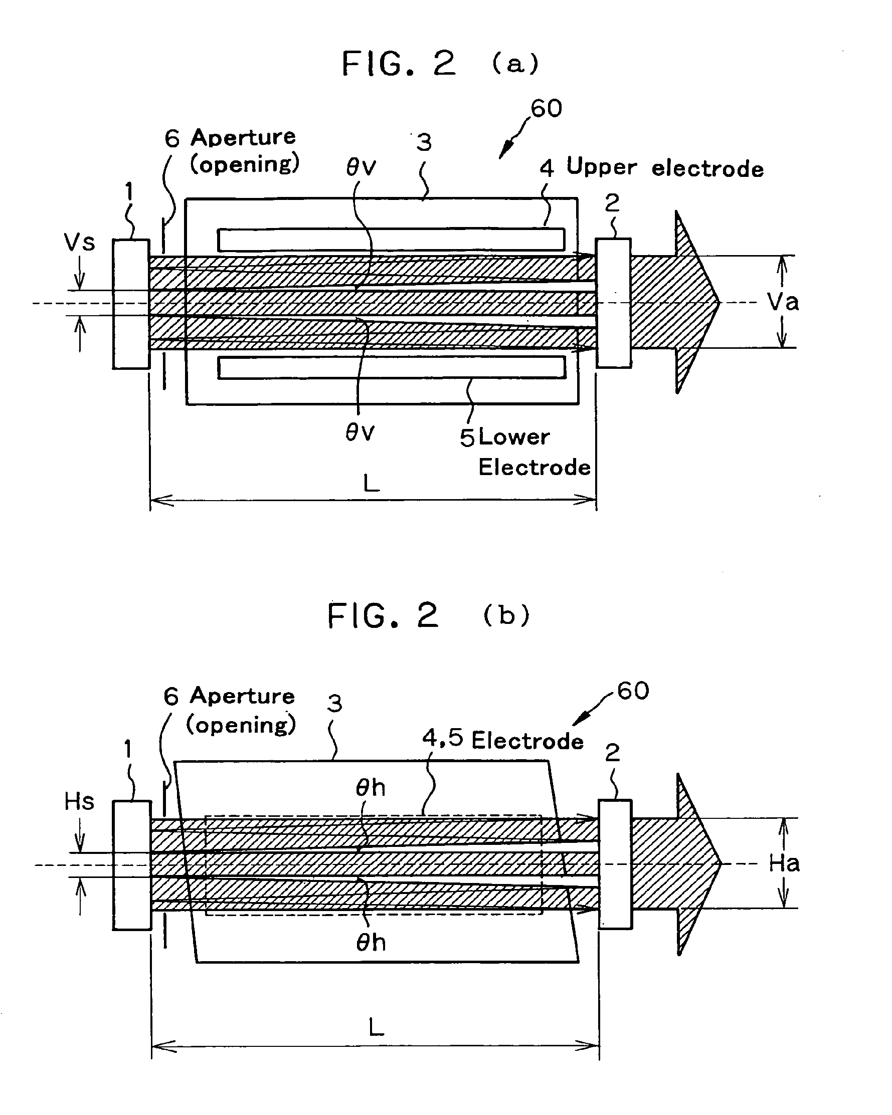
[0196] As described with reference to FIG. 73, it has been found that in the MOPO system comprising an oscillation-stage laser and an amplification-stage laser in which laser light (seed light) oscillated out of the oscillation-stage laser is entered for amplification, and which comprises a resonator comprising an input side mirror and an output side mirror, if the resonator in the amplification-stage laser is configured as a stable resonator, it is then possible to achieve a low spatial coherence equivalent to that of the oscillation-stage laser.

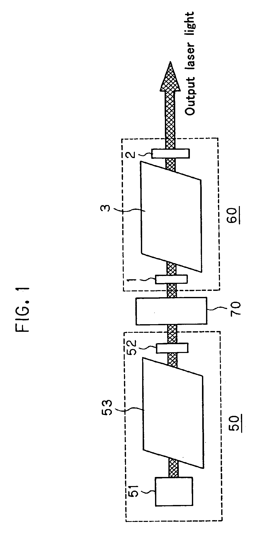
[0197]FIG. 1 is illustrative in schematic of the basic arrangement of the two-stage laser system for aligners according to the invention. The two-stage laser system for aligners according to the invention is a MOPO system as described above, which comprises an oscillation-stage laser (MO: Master Oscillator) 50, and a...


PUM

PropertyMeasurementUnit
angleaaaaaaaaaa
wavelengthaaaaaaaaaa
diameteraaaaaaaaaa

Abstract

The invention relates to a two-stage laser system well fit for semiconductor aligners, which is reduced in terms of spatial coherence while taking advantage of the high stability, high output efficiency and fine line width of the MOPO mode. The two-stage laser system for aligners comprises an oscillation-stage laser (50) and an amplification-stage laser (60). Oscillation laser light having divergence is used as the oscillation-stage laser (50), and the amplification-stage laser (60) comprises a Fabry-Perot etalon resonator made up of an input side mirror (1) and an output side mirror (2). The resonator is configured as a stable resonator.

Description

ART FIELD [0001] The present invention relates generally to a two-stage laser system for aligners, and more particularly to a two-stage laser system well fit for semiconductor aligners, which is reduced in terms of spatial coherence. BACKGROUND ART [0002] So far, two-stage laser systems comprising an oscillation-stage laser and an amplification-stage laser adapted to amplify laser light emitted out of the oscillation-stage laser have been known so far in the art for the purpose of obtaining high outputs. Two modes, MOPA (Master Oscillator Power Amplifier) and MOPO (Master Oscillator Power Oscillator) are known for double-chamber laser systems. The former is a mode having no resonator in the amplification stage, and the latter is a mode having an unstable resonator in the amplification stage. The MOPA mode and the MOPO mode have merits and demerits over each other. MOPA [0003] (a) Low spatial coherence (merit). That is, given the same share quantity (pinhole-to-pinhole spacing) in t...

Claims


Application Information

Patent Timeline
Patent Type & Authority Applications(United States)
IPC IPC(8): H01S3/082G03F7/20H01S3/23
CPCG03F7/70025H01S3/083H01S3/2308
Inventor WAKABAYASHI, OSAMUARIGA, TATSUYAKUMAZAKI, TAKAHITOSASANO, KOTARO
Owner GIGAPHOTON
Learn More