System and Method for the Adjustment of Compensation Applied to a Signal Using Filter Patterns

a filter pattern and compensation technology, applied in the field of signal communication, can solve problems such as attenuation of signals from phenomena, and achieve the effects of avoiding delay in convergence time, potential instability, and improving component sensitivity

Inactive Publication Date: 2007-12-27
FUJITSU LTD
View PDF26 Cites 48 Cited by
  • Summary
  • Abstract
  • Description
  • Claims
  • Application Information

AI Technical Summary

Benefits of technology

[0013]Yet another technical advantage of particular embodiments is correcting for a potential false locking problem in conjunction with adjusting for residual DC offset observed in output signals. The false locking problem arises when a clock recovery and an offset canceller interact improperly, leading to the sampled boundary and data values to be interchanged. Particular embodiments correct for the false locking problem by adjusting DC offset compensation based on the high or low value of each boundary value, regardless of whether the boundary value is between successive data values comprising a transition. To correct for the false locking problem in (quasi-) periodic signals where re-sampling is used, particular embodiments first monitor data DC imbalance (a proxy for the false locking problem) using output signal values. If an imbalance is detected, DC offset compensation is adjusted based on the detected imbalance. If an imbalance is not detected, DC offset compensation is adjusted based on the high or low values of only those boundary values between successive data values comprising transitions. In this way, data DC imbalance may vary within an acceptable range, even if re-sampling is used for a (quasi-) periodic data sequence.
[0014]Still another technical advantage of particular embodiments is using output signal values to cancel offsets in each path of a multi-path equalizer. In particular embodiments, offsets in each path may be cancelled without using any additional circuitry to monitor internal residual offset in the equalizer. In addition, in particular embodiments, the offset cancel control may be used during operation of the equalizer (i.e., without turning off any part of the equalizer circuit) and during receipt of a signal comprising real data traffic (and not only during receipt of a signal carrying only test traffic). By making adjustments to DC offset compensation during receipt of a signal comprising real data traffic (and not test traffic only), component sensitivity may be improved during receipt of the real data traffic.
[0015]Another technical advantage of particular embodiments where re-sampling is used is avoiding any locking of the re-sampling period with the period of a (quasi-) periodic signal. When locking occurs, the data patterns observed in re-sampled data may be different than the data patterns in the entire (quasi-) periodic signal, potentially skewing the control actions performed by the equalizer controller. Particular embodiments may avoid locking by varying the point at which the (quasi-) periodic signal is re-sampled in each re-sampling cycle.
[0016]Yet another technical advantage of particular embodiments is decoupling multiple control loops, such as, for example, the adaptive equalizer control and the offset canceller. Decoupling the multiple control loops may avoid delay in convergence time and potential instability in the control loops. Particular embodiments may decouple multiple control loops by making the loops insensitive to each other. For example, the adaptive equalizer control may be made insensitive to residual offset, and the offset canceller may be made insensitive to residual inter-symbol interference (ISI). To make the adaptive equalizer control and offset canceller insensitive to each other, in particular embodiments, two sets of complementary data patterns may be used in a balanced manner by the adaptive equalizer control and the offset canceller.
[0017]Still another technical advantage of particular embodiments is generating a particular average value of a binary objective variable (e.g., ISI level, equalization level, or other suitable objective variable) in an equilibrium state in a bang-bang control system that does not necessarily converge to zero, as is the case in typical bang-bang control systems. The binary objective variable may be, for example, the inverted correlation function applied to a boundary value between opposite data values and to the data value 1.5 bits (or symbols) before the boundary value. In particular circumstances, the optimal average value of a binary objective variable (e.g., ISI level, equalization level, or other suitable objective variable) in equilibrium may be greater or less than zero depending on various conditions, such as, for example, channel loss and the incoming signal itself. Thus, embodiments that generate an average value of the binary objective variable that converges closer to the optimal average value (than does zero) may be advantageous.
[0018]Another technical advantage of particular embodiments is dynamically generating a control target for an average value of a binary objective variable (e.g., ISI level, equalization level, or other suitable objective variable) in an equilibrium state. In particular embodiments, the optimal average ISI level is likely to be high for a high loss channel and low for a low loss channel. Thus, embodiments comprising a control target for the average value of a binary objective variable that dynamically varies with the value of the control variable may be advantageous.

Problems solved by technology

When signals are communicated over communication media, the signals may suffer attenuation from phenomena such as skin effect and dielectric absorption.

Method used


Image

  • System and Method for the Adjustment of Compensation Applied to a Signal Using Filter Patterns
  • System and Method for the Adjustment of Compensation Applied to a Signal Using Filter Patterns
  • System and Method for the Adjustment of Compensation Applied to a Signal Using Filter Patterns

Examples


Embodiment Construction

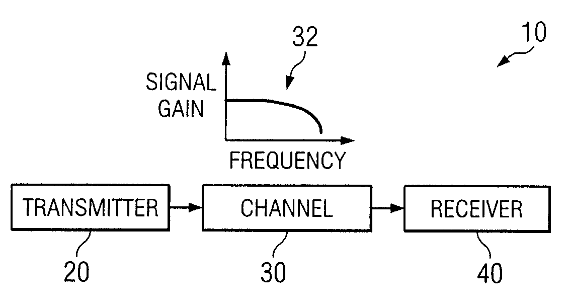
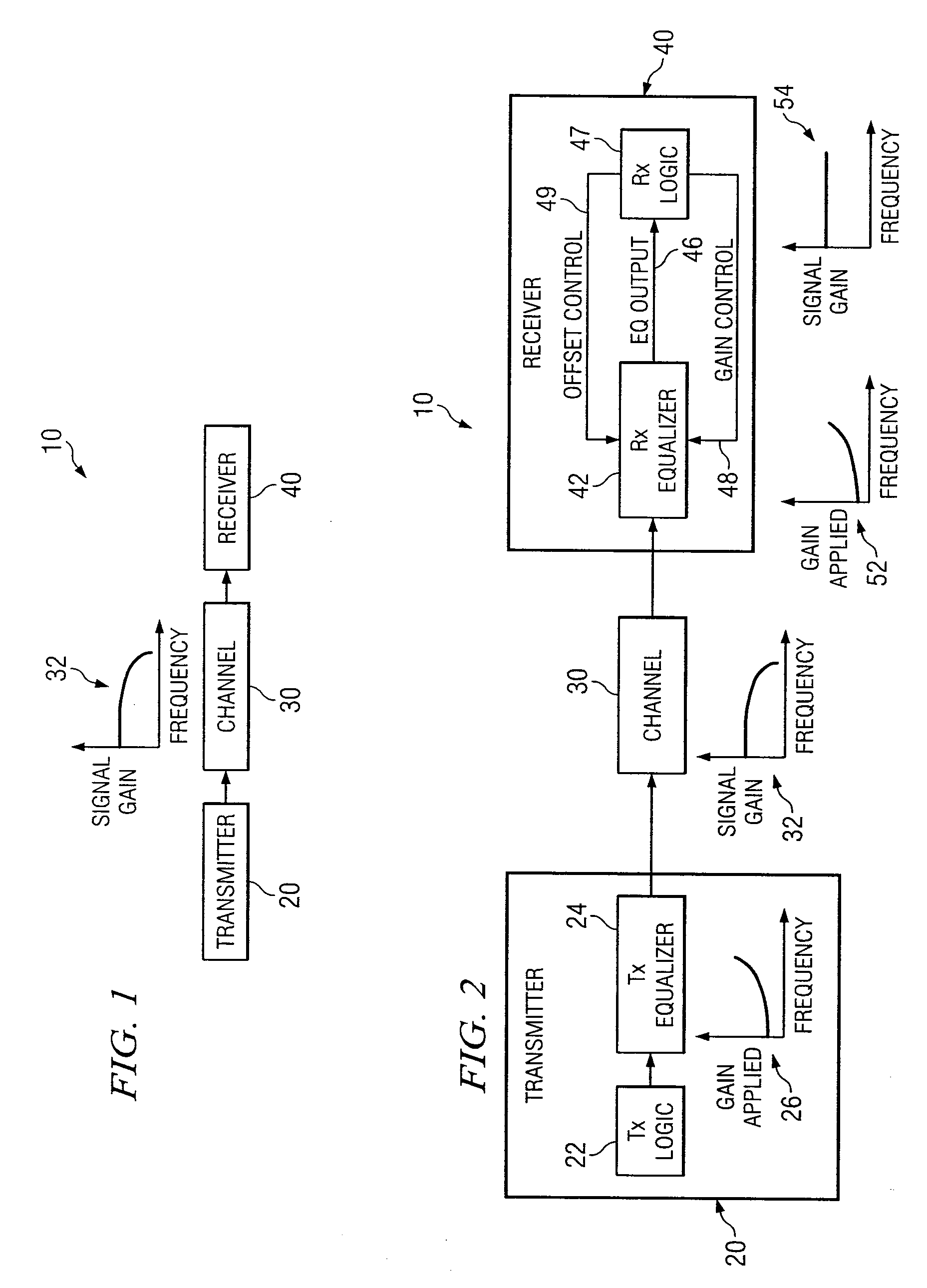
[0072]FIG. 1 is a block diagram illustrating an example digital signal transmission system 10. Digital signal transmission system 10 comprises transmitter 20, communication channel 30, and receiver 40. Transmitter 20 may comprise any suitable transmitter operable to transmit signals carrying digital information to receiver 40 over channel 30. In particular embodiments, transmitter 20 may communicate information at relatively fast rates. Channel 30 may comprise any suitable channel or other communication medium. Channel 30 may include, for example, a cable carrying a signal, an insulator insulating the cable, packaging around the cable, and / or connectors. Channel 30 is operable to receive signals from transmitter 20 and forward these signals to receiver 40. Receiver 40 may comprise any suitable receiver operable to receive signals from transmitter 20 over channel 30 and process the digital information in the received signals suitably.

[0073]In typical digital signal transmission syste...


PUM


Abstract

In one embodiment of the present invention, a method for adjusting a signal includes applying at least one of a loss compensation for frequency-dependent distortion and an offset compensation for DC-offset distortion to a data signal before or after the distortion occurs to generate an output signal. The method also includes, using a clock signal, sampling the output signal to generate a plurality of data values and an error value, each data value comprising either a high value or a low value based on the sampling of the output signal, the error value indicating residue of the distortion based on the sampling of the output signal. The method further includes selecting one or more filter patterns from a set of a plurality of filter patterns, each filter pattern comprising a plurality of data values. The method also includes monitoring the output signal for one or more patterns of data values corresponding to the one or more selected filter patterns. The method further includes detecting a pattern of data values in the output signal corresponding to one of the one or more selected filter patterns. The method also includes adjusting the at least one of the loss compensation and the offset compensation applied to the data signal based on the error value.

Description

CROSS-REFERENCE TO RELATED APPLICATION[0001]This application claims the benefit of priority under 35 U.S.C. § 119(e) of U.S. Provisional Application entitled “Adaptive Equalizer,” Ser. No. 60 / 803,451 filed May 30, 2006.TECHNICAL FIELD OF THE INVENTION[0002]This invention relates generally to signal communication and, more particularly, to a system and method for the adjustment of compensation applied to a signal using filter patterns.BACKGROUND OF THE INVENTION[0003]When signals are communicated over communication media, the signals may suffer attenuation from phenomena such as skin effect and dielectric absorption. Signal receivers may include equalizers that compensate for this attenuation in order to improve the accuracy and efficiency of signal communication. It is desirable for the amount of compensation applied by equalizers to match the level of attenuation due to the media as closely as possible, in order to keep the output characteristics of the signal consistent independen...

Claims


Application Information

Patent Timeline
Patent Type & Authority Applications(United States)
IPC IPC(8): G08C25/00H04L1/00H03M13/00G06F11/00G06F11/30
CPCH04L25/063H04L25/03885
Inventor HIDAKA, YASUO
Owner FUJITSU LTD
Why Eureka
Try Eureka