System for Nano Position Sensing in Scanning Probe Microscopes using an Estimator

Inactive Publication Date: 2008-01-03
KEYSIGHT TECH
View PDF6 Cites 3 Cited by
  • Summary
  • Abstract
  • Description
  • Claims
  • Application Information

AI Technical Summary

Benefits of technology

[0003]In accordance with the invention, an estimator is used in the controller portion of a scanning probe microscope to provide precise position estimates of the probe tip which is controlled in the vertical direction by a microelectromechanical system (MEMS) actuator. The precise position estimates typically enhance the ability of the scanning probe microscope to follow the surface and typically provide improved measurements of the surface topography.

Problems solved by technology

This typically limits the bandwidth and accuracy of the position estimate to that of the control loop itself.

Method used


Image

  • System for Nano Position Sensing in Scanning Probe Microscopes using an Estimator
  • System for Nano Position Sensing in Scanning Probe Microscopes using an Estimator
  • System for Nano Position Sensing in Scanning Probe Microscopes using an Estimator

Examples


Embodiment Construction

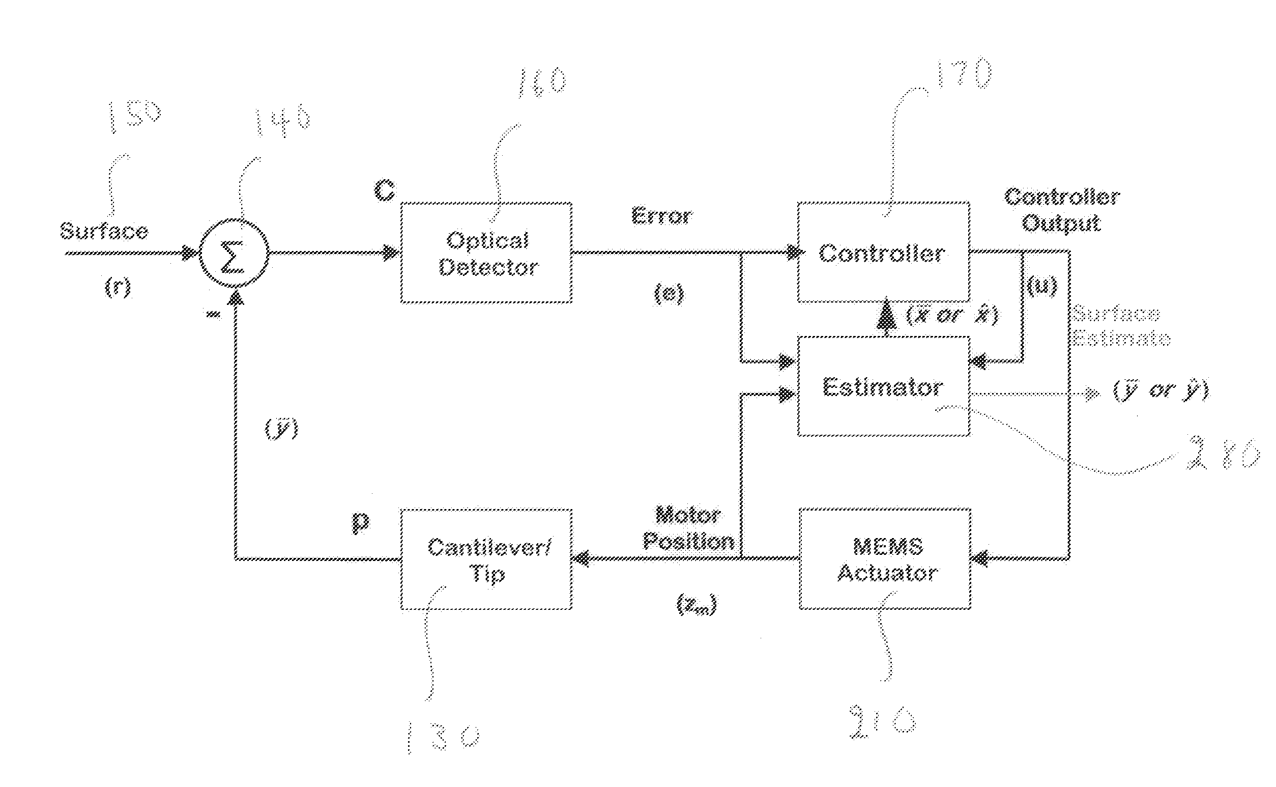
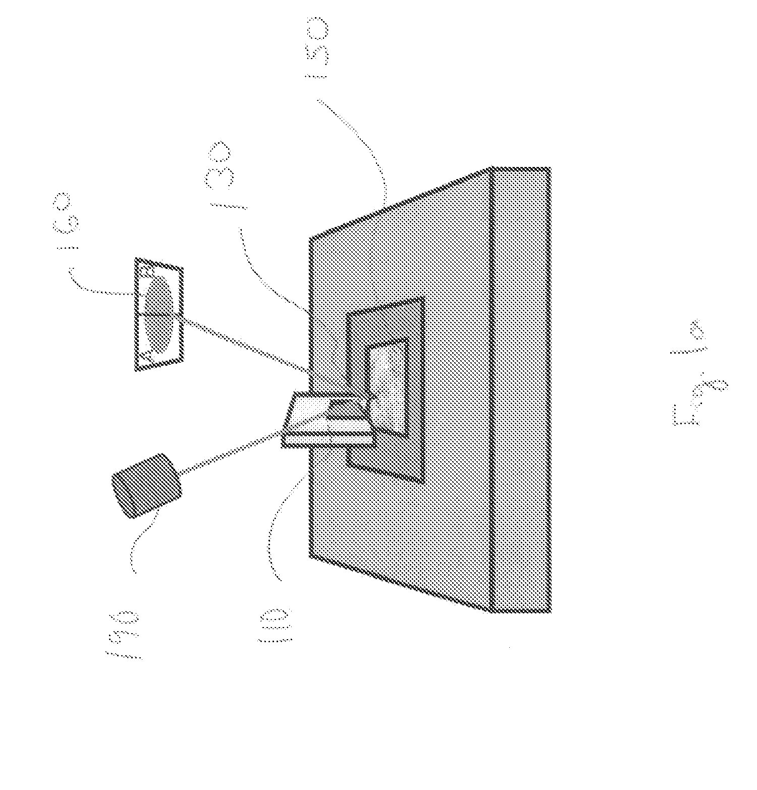
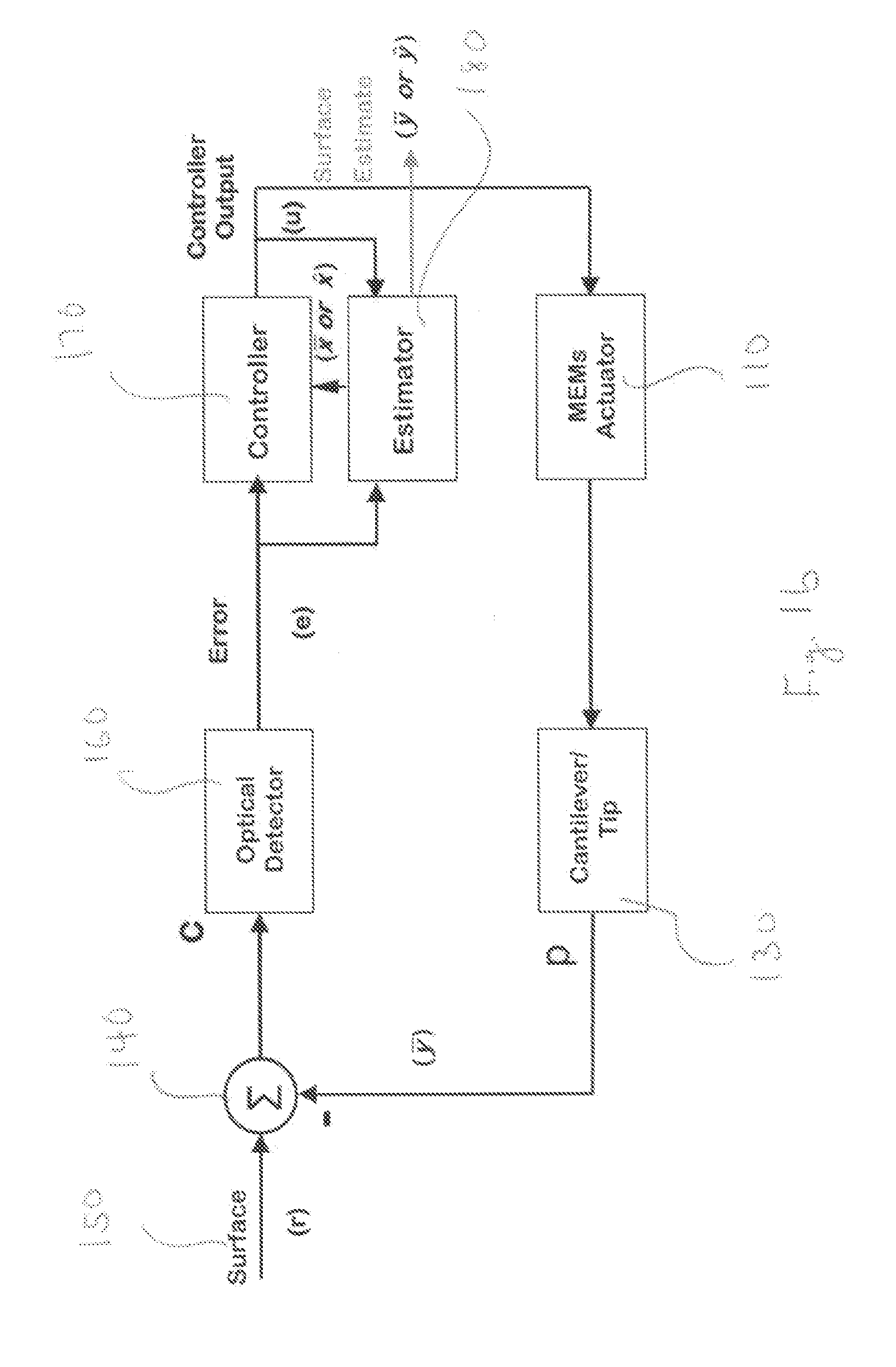
[0007]FIG. 1a shows a simplified view of the corresponding AFM physical apparatus in accordance with the invention with optical detector 160, MEMS actuator 110, laser source 190, cantilever / probe tip 130 and surface 150.

[0008]FIG. 1b shows a block diagram for a AFM using MEMS actuator 110 for vertical control and estimator 120 in accordance with the invention. Optical detector 160 is sensitive to the deflection of cantilever / probe tip 130 as cantilever / probe tip 130 moves over surface 150. The input to optical detector 160 is the interaction between the surface elevation (r) on surface 150 and the position (p) of cantilever / probe tip 130 which results in movement of the reflected laser spot on optical detector 160. The control system shown is a single input, single output system or SISO.

[0009]The use of MEMS actuator 110 in place of a piezoelectric actuator typically allows a quicker actuator response and avoids the hysteresis effects typically associated with piezoelectric actuator...


PUM


Abstract

In accordance with the invention, an estimator is used in the controller portion of a scanning probe microscope to provide precise position estimates of the probe tip which is controlled in the vertical direction by a microelectromechanical system (MEMS) actuator. The precise position estimates typically enhance the ability of the scanning probe microscope to follow the surface and typically provide improved measurements of the surface topography.

Description

BACKGROUND[0001]Scanning probe microscopes are characterized by the nature of the local probe and its interaction with the surface. Examples of scanning probe microscopes are scanning tunneling microscopes, magnetic force microscopes, electrostatic force microscopes, scanning force microscopes and atomic force microscopes. Atomic force microscopes (AFMs) typically image a surface by applying a thin probe tip attached to the end of a flexible cantilever to the surface to be imaged. As the probe tip moves across the surface, variations in the probe tip height are detected, typically, by the tracking of a laser spot on the cantilever. Deflections of the cantilever due to height variations of the probe tip result in movement of the reflected laser spot on the optical detector. In a constant force mode application, a servo-system is used to keep movement of the reflected laser spot on the optical detector to a minimum by moving the actuator that controls the cantilever to keep the cantil...

Claims


Application Information

Patent Timeline
IPC IPC(8): G01B5/28G01Q10/06G01Q20/02
CPCB82Y35/00G01Q10/04G01Q20/02G01Q10/065
Inventor ABRAMOVITCH, DANIEL Y.
Owner KEYSIGHT TECH
Why Eureka
Try Eureka