
Method for manufacturing semi-hard magnetic material and semi-hard magnetic material

a technology of magnetic material and magnetic material, which is applied in the direction of magnetic bodies, heat treatment apparatus, furnaces, etc., can solve the problems of loss of function as crime prevention sensor, small magnetic field given to the magnetostrictive strip in the magnetized state, and difficulty in demagnetization, etc., to facilitate coercive force adjustment, high residual magnetic flux density, and square

Inactive Publication Date: 2008-01-03
HITACHI METALS LTD
View PDF4 Cites 12 Cited by
  • Summary
  • Abstract
  • Description
  • Claims
  • Application Information

AI Technical Summary

Benefits of technology

[0034] According to the present invention, the final manufacturing process of the semi-hard magnetic material is the heat treatment generating reverse transformed austenite, whereby it facilitates the adjustment of the coercive force in comparison with the case where the final process is cold rolling. Therefore, the present invention provides an important technique in industrially manufacturing a semi-hard magnetic material.
[0035] Furthermore, since the semi-hard magnetic material of the present invention can obtain a coercive force in a desired range, a high residual magnetic flux density and a squareness ratio by adjusting the amount of reverse transformed austenite and hardness, the semi-hard magnetic material can be used, for example as a bias material of a crime prevention sensor.

Problems solved by technology

In this case, if the coercive force of the material which composes the bias is too large, it is difficult to realize demagnetization.
On the contrary, if the coercive force is too low, it is easy to realize demagnetization, but there is a problem that the magnetic field given to the magnetostrictive strip in the magnetized state becomes small.
Furthermore, when a tiny reverse magnetic field is applied to the bias, the function as the crime prevention sensor is lost and this deteriorates the reliability.

Method used


Image

  • Method for manufacturing semi-hard magnetic material and semi-hard magnetic material
  • Method for manufacturing semi-hard magnetic material and semi-hard magnetic material
  • Method for manufacturing semi-hard magnetic material and semi-hard magnetic material

Examples


example 1

[0103] A semi-hard magnetic material No. 1 was obtained by a vacuum melting using facilities for mass production on an industrial scale, and hot forging at 1100° C. The chemical composition of the material No. 1 is shown in table 1.

[0104] [Table 1]

TABLE 1(mass %)No.CSiMnPSNiMo[O][N]Balance10.0020.290.310.0050.00220.134.141217Fe andinevitableimpurities

Note)

Amount of element enclosed by brackets denotes ppm.

[0105] A semi-hard magnetic material having the composition of No. 1 was subjected to hot rolling at 1100° C., finished to a thickness of 25 mm, further kept in an Ar atmosphere at 830° C. for 1 hour and subjected to air cooling.

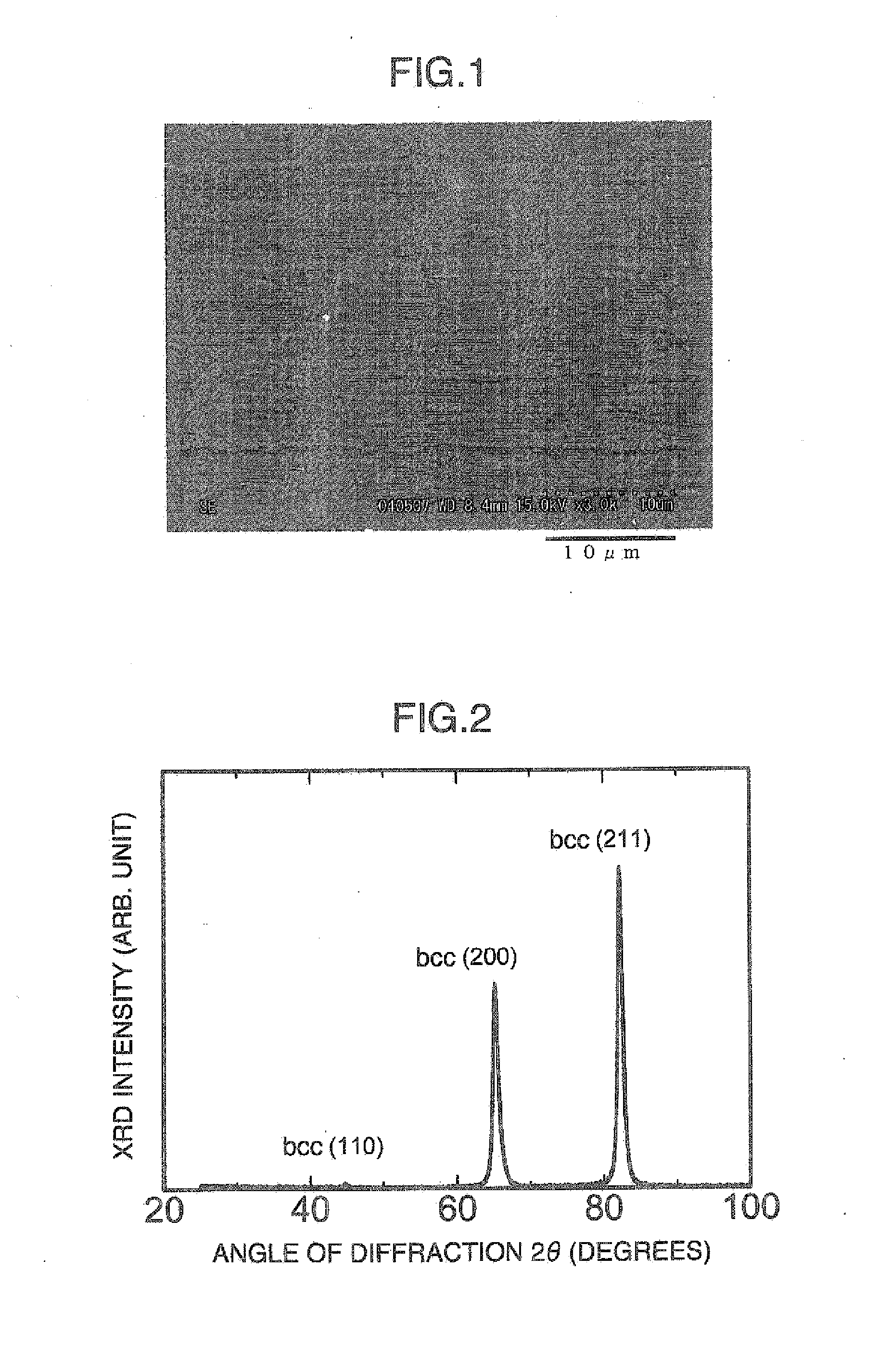
[0106] The amount of martensite after hot rolling was 98.8% and the amount of martensite after heat treatment was 99.0%. As for the method of measuring the amount of martensite, it was measured based on the above described integration intensity ratio of the X-ray diffraction peaks. Both metallic structures after hot rolling and after heat treatment were...

example 2

[0136] Based on the result of Example 1, an industrial prototype of a semi-hard magnetic material was manufactured in the following manufacturing processes.

[0137] A raw material for a semi-hard magnetic material was obtained through a vacuum melting using mass production facilities on an industrial scale, and hot forging at 1100° C. After hot rolling on the material at 1100° C. to a thickness of 2.5 mm, the material was subjected to heat treatment in a vacuum furnace. The chemical composition of this semi-hard magnetic material is the same as that shown in Table 1.

[0138] As the heat treatment condition, the material was heated at 830° C., and kept for one hour, and then rapidly cooled by N2 gas. The amount of martensite after hot working was 98.9% and that after heat treatment was 99.0%. The amount of martensite was measured based on the above described X-ray diffraction integration intensity ratios. Both metallic structures after hot rolling and after heat treatment were recrysta...

example 3

[0147] Based on the result of Example 1, an industrial prototype of a semi-hard magnetic material was manufactured in the following manufacturing processes.

[0148] A raw material for a semi-hard magnetic material was obtained through a vacuum melting using mass production facilities on an industrial scale, and hot forging at 1100° C. This raw material was subjected to hot rolling at 1100° C. to a thickness of 2.5 mm. The chemical composition of the semi-hard magnetic material is the same as that shown in Table 1.

[0149] Next, the material was directly subjected to cold rolling at a reduction of 98% without heat treatment to reduce processes, and a plate material having a thickness of 0.05 mm was obtained. It was confirmed that this plate material also had 100% of martensitic structure and an extended structure.

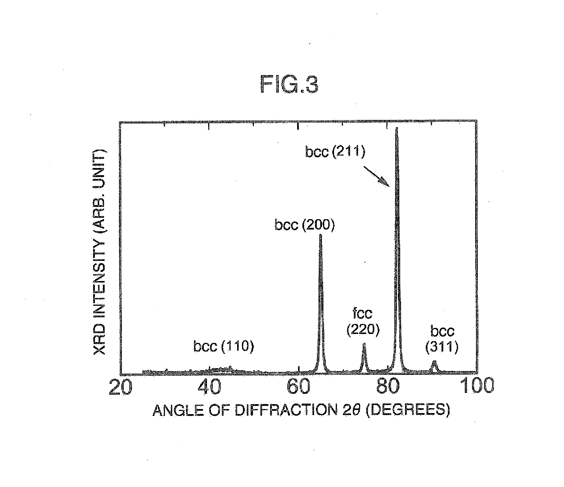
[0150] Specimens were cut out from the plate material as in the cases of Examples 1 and 2. They were then subjected to heat treatment for generating reverse transformed auste...


PUM

PropertyMeasurementUnit
mass %aaaaaaaaaa
mass %aaaaaaaaaa
coercive force Hcaaaaaaaaaa

Abstract

The present invention provides a method of manufacturing a semi-hard magnetic material comprising, sequentially: preparing a raw material of consisting essentially of 10.0 to 25.0% of Ni:, 2.0 to 6.0% of Mo and the balance being Fe and inevitable impurities, in mass %; heat-treating or hot-working the raw material so that it has not less than 50% of martensitic structure; cold-working the material at a reduction of area of not less than 50% so that it has a extended structure including not less than 95% of a martensitic structure; and heat-treating the material in a range of 400 to 570° C. so as to generate more than 0% but less than 30.0% of reverse-transforraed austenitic structure. The semi-hard magnetic material manufactured using this method can obtain a coercive force of 1000 to 5600 A / m.

Description

BACKGROUND OF THE INVENTION [0001] (1) Field of the Invention [0002] The present invention relates to a method of manufacturing a semi-hard magnetic material, for example used as a bias material for a crime prevention sensor, and to a semi-hard magnetic material. [0003] (2) Description of Related Art [0004] A magnetic sensor tag attached to goods at large-sized mass merchandisers or the like for preventing burglary (which is referred to as a “crime prevention sensor” hereinafter) is composed of a resonating magnetostrictive strip and a bias which gives a magnetic field thereto. [0005] The system of the crime prevention sensor has a function that the magnetostrictive strip resonates and an alarm sounds when somebody attempts to take a product out of a shop without paying a charge. When a charge is duly paid, however, the resonance frequency is necessary to be changed so as not cause the magnetostrictive strip to resonates To change the resonance frequency of the magnetostrictive stri...

Claims


Application Information

Patent Timeline
Patent Type & Authority Applications(United States)
IPC IPC(8): H01F1/01C21D6/00
CPCC21D6/00H01F1/14708C21D9/46C21D8/12
Inventor YOKOYAMA, SHINICHIRO
Owner HITACHI METALS LTD
Learn More