Sheet roller

a sheet roller and roller body technology, applied in the field of sheet rollers, can solve the problems of difficult mounting to the sheet roller, the thickness of the roller body b>51/b> is inevitably increased, and the limit of the thickness of the roller sheet is difficult to achieve the effect of compactness and thinness

Active Publication Date: 2008-01-03
NAUTILUS HYOSUNG
View PDF5 Cites 11 Cited by
  • Summary
  • Abstract
  • Description
  • Claims
  • Application Information

AI Technical Summary

Benefits of technology

[0019] An aspect of the present invention provides a sheet roller capable of achieving compactness and thinness thereof.
[0020] Another aspect of the present invention provides a sheet roller capable of improving space usability and design freedom of an automatic transaction machine where the sheet roller is mounted.
[0021] Still another aspect of the present invention provides a sheet roller capable of improving productivity and workability thereof and readily being mounted in an appropriate position regardless of an order of assembly with other components.
[0022] Yet another aspect of the present invention provides a sheet roller capable of facilitating maintenance and repair thereof without separation / disassembly of other components.
[0033] In this instance, a rotation restriction protrusion is formed on at least an inner peripheral surface of the first and the second roller bodies, and a rotation restriction groove is formed on an outer peripheral surface of the rotation shaft, the rotation restriction groove receiving the rotation restriction protrusion. depending upon embodiments, a coupling hole having a non-circular shaped-rotation restriction surface may be formed on the inner peripheral surface of the sheet roller so as to correspond to a rotation restriction surface of the rotation shaft so that the relative rotation of the sheet roller to the rotation shaft is prevented.

Problems solved by technology

A large amount of cash is deposited and dispensed according to the increase in transaction amounts, and accordingly, undesirable problems are caused in the automatic transaction machine due to mutual movement and interference in positioning of the large amount of cash.
However, the conventional sheet roller 50 described above has a problem in that it has a limitation in reducing thickness of the roller sheet while maintaining a predetermined shape and strength thereof.
As a result, there occurs a problem in that a thickness of the roller body 51 is inevitably increased by a depth of the coupling groove 51 a.
Further, the conventional sheet roller 50 has a problem in that the elastic sheet 53, having different thicknesses depending on mounting position, design configuration, and the like, is difficult to be mounted to the sheet roller 50.
In addition, the conventional sheet roller 50 has a problem in that, in terms of structural properties, the sheet roller 50 has to be mounted to the rotation shaft 43 in accordance with the order of assembly with components such as the transfer roller, and the like, before the rotation shaft 43 is mounted, and thus deteriorating productivity and workability thereof.

Method used


Image

  • Sheet roller
  • Sheet roller
  • Sheet roller

Examples


Embodiment Construction

[0046] Reference will now be made in detail to exemplary embodiments of the present invention, examples of which are illustrated in the accompanying drawings, wherein like reference numerals refer to the like elements throughout. The exemplary embodiments are described below in order to explain the present invention by referring to the figures.

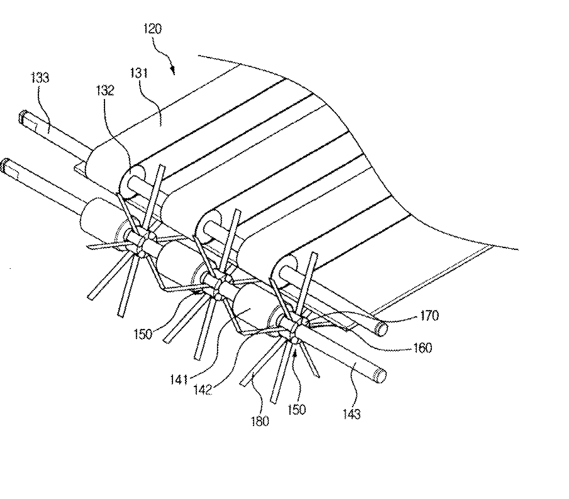
[0047]FIG. 3 is a side view illustrating a structure of an automatic transaction machine where a sheet roller according to an exemplary embodiment of the present invention is mounted, and FIG. 4 is a perspective view illustrating a state where a sheet roller according to an exemplary embodiment of the present invention is mounted.

[0048] As illustrated in FIGS. 3 and 4, an automatic transaction machine where a sheet roller according to the present exemplary embodiment of the invention includes a transfer device 120 transferring a paper medium such as a cash from a storage part such as a cash cassette, a money dispensing part 110 mounted adjac...


PUM


Abstract

Disclosed is a sheet roller capable of achieving compactness and thinness, and improves space usability and design freedom. The sheet roller includes a roller body coupled with the rotation shaft, a plurality of coupling members coupled with a side surface of the roller body in order to surround a part of an outer peripheral surface of the roller body, and disposed on the outer peripheral surface of the roller body in such a manner as to be spaced apart from one another, and an elastic sheet interposed between the roller body and each of the plurality of coupling members. The roller body is formed to have a predetermined thickness thereof while maintaining a predetermined shape and strength thereof, and thus, improving space usability and the design freedom of an automatic transaction machine where the sheet roller is mounted.

Description

CROSS-REFERENCE TO RELATED APPLICATION [0001] This application claims the benefit of Korean Patent Application No. 10-2006-0061093, filed on Jun. 30, 2006, in the Korean Intellectual Property Office, the entire disclosure of which is incorporated herein by reference. BACKGROUND OF THE INVENTION [0002] 1. Field of the Invention [0003] The present invention relates to a sheet roller mounted to an automatic transaction machine, and more particularly, to a sheet roller which achieves compactness and thinness, and improves space usability and design freedom. [0004] 2. Description of Related Art [0005] In general, an automatic transaction machine provides basic financial services such as a money reception / dispensing without a bank teller regardless of time and location. The automatic transaction machine is classified into a cash dispensing machine and a cash depositing / dispensing machine depending on money reception / dispensing. Recently, the automatic transaction machine has been used for...

Claims


Application Information

Patent Timeline
Patent Type & Authority Applications(United States)
IPC IPC(8): B65H29/54
CPCB65H29/14B65H2404/1114B65H2404/261B65H2404/264B65H2601/324B65H2220/09B65H2701/1912G07D2211/00G07F19/201G07D11/16
Inventor LEE, DONG SIKLEE, WON JOONHAN, JOONG HYUK
Owner NAUTILUS HYOSUNG
Why Eureka
Try Eureka