Method for generating a reference current and a related feedback generator

a reference current and feedback technology, applied in the direction of electrical variable regulation, process and machine control, instruments, etc., can solve the problem that the current generator may occupy less silicon area, and achieve the effect of less silicon area and good performan

Inactive Publication Date: 2008-01-03
STMICROELECTRONICS SRL
View PDF10 Cites 7 Cited by
  • Summary
  • Abstract
  • Description
  • Claims
  • Application Information

AI Technical Summary

Benefits of technology

[0006]This invention may provide a reference current generator with good performance in terms of insensitivity to fluctuations in the supply voltage, noise rejection in the supply voltage, stability, and insensitivity to temperature variations. Moreover, this current generator may occupy less silicon area than known generators with similar performance.

Problems solved by technology

Moreover, this current generator may occupy less silicon area than known generators with similar performance.

Method used


Image

  • Method for generating a reference current and a related feedback generator
  • Method for generating a reference current and a related feedback generator
  • Method for generating a reference current and a related feedback generator

Examples


Embodiment Construction

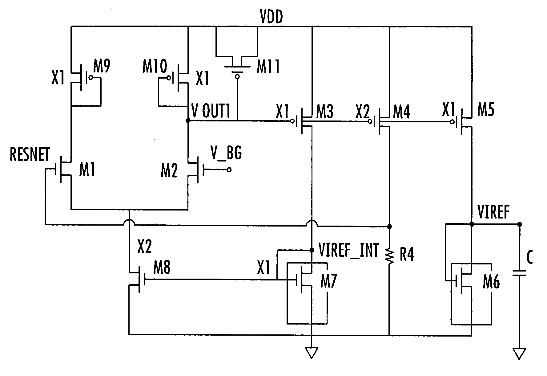
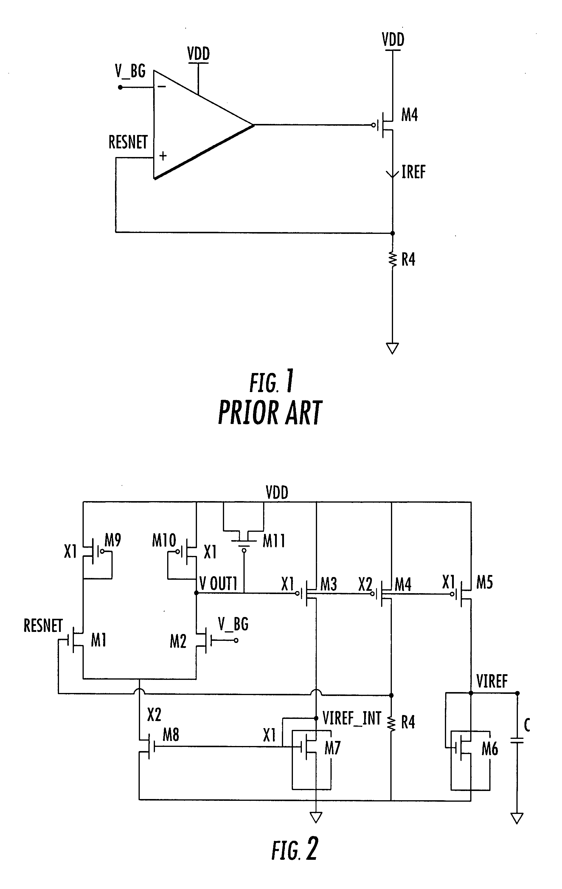
[0014]Referring to the circuit diagram of a constant current generator depicted in FIG. 2, as in the prior art diagram of FIG. 1, it comprises a differential amplifier that is input with the bandgap reference voltage V_bg and the feedback voltage Resnet. A transistor M4 is controlled by the output voltage Vout1 connected in series with a feedback resistor R4, in which the reference current Iref flows and on which the feedback voltage Resnet is produced.

[0015]The illustration of FIG. 2 includes a second current path for biasing the differential amplifier with either a scaled / amplified or identical replica of the current Iref flowing through the resistor R4. According to this embodiment of the amplifier, this is done by the transistor M3 and the diode-connected transistor M7 forming a current mirror with the bias transistor MS of the differential amplifier. The transistor M3 may be a scaled replica of the transistor M4 and is controlled by the output voltage Vout1. As a consequence, t...


PUM


Abstract

A feedback generator of a reference current may include a differential amplifier having a first input for a reference voltage, and a second input for a feedback voltage and generating an output voltage. The feedback generator may also include a first conduction path including a feedback resistor with the feedback voltage applied thereon, and a first transistor controlled by the output voltage and forcing through the feedback resistor the reference current. The feedback generator may also include a second conduction path coupled to the differential amplifier and biasing the differential amplifier based upon the reference current.

Description

FIELD OF THE INVENTION[0001]This invention relates to a current generator and, more particularly, to a generator of a constant reference current.BACKGROUND OF THE INVENTION[0002]Current generators employing active devices are commonly used in integrated analog circuits as biasing elements, active loads in amplification stages, and other similar applications. The use of current generators as biasing elements may be useful for fabricating circuits with performance that is substantially independent of fluctuations of the supply voltage and of temperature. The most frequently used parameters for evaluating performances of a current generator are sensitivity to supply voltage and sensitivity to temperature.[0003]Another parameter for evaluating the performance of a current generator is rejection of wide frequency spectrum noise that is often present on supply lines, being caused by, for example, digital circuits, oscillators, charge pumps, and similar circuits connected to the same suppl...

Claims


Application Information

Patent Timeline
Patent Type & Authority Applications(United States)
IPC IPC(8): G05F3/20
CPCG05F1/46
Inventor CONTE, ANTONINOMICCICHE, MARIOSCAVO, VITTORIOGRASSO, ROBERTO ROSARIO
Owner STMICROELECTRONICS SRL
Why Eureka
Try Eureka