
Direct liquid jet impingement module for high heat flux electronics packages

a technology of electronic packages and liquid jets, applied in the direction of cooling/ventilation/heating modifications, semiconductor/solid-state device details, semiconductor devices, etc., can solve problems such as device performance challenges, electronic and mechanical failures that will affect overall system performance, and environmental performance increas

Inactive Publication Date: 2008-01-03
IBM CORP
View PDF10 Cites 27 Cited by
  • Summary
  • Abstract
  • Description
  • Claims
  • Application Information

AI Technical Summary

Problems solved by technology

Despite many of the advantages associated with this industry goal, providing many such components in a small footprint create device performance challenges.
One such challenge has to do with thermal management of the overall environment.
Heat dissipation, if unresolved, can result in electronic and mechanical failures that will affect overall system performance, no matter what the size of the environment.
In many computing environments, especially those that incorporate microprocessors and other such components, the microprocessors inside the environment increase in performance, the active circuitry of a chip is driven to smaller devices and higher power consumption.
Higher power consumption and smaller devices lead to high heat loads and high heat fluxes.
Reliability limitations dictate that the temperature of the devices may not exceed a known maximum value.
The prior art has struggled with designing high-performance cooling solutions that can dissipate this heat.
Unfortunately, providing greater airflow is not always possible.
Many limitations exist that must be taken into consideration, among which are both noise (acoustic) considerations as well as power concerns.
Liquid cooling, however, is also limited by several factors.
Immersion cooled modules have the limitation that the critical heat flux of the dielectric refrigerants is relatively low, limiting the chip heat flux.
Cold plate cooled modules have the limitation that a thermal interface material must be used, limiting the heat transfer capabilities of the module.

Method used


Image

  • Direct liquid jet impingement module for high heat flux electronics packages
  • Direct liquid jet impingement module for high heat flux electronics packages
  • Direct liquid jet impingement module for high heat flux electronics packages

Examples


Embodiment Construction

[0017] The present invention provides for a direct liquid jet impingement module that eliminates the need for a thermal interface material. As will be discussed in detail below, the direct liquid jet impingement module of the present invention is capable of utilizing a variety of coolants, including but not limited to water based coolants which take advantage of superior thermal properties in contrast to dielectric liquids. This is partly due to the unique sealing structures used in this invention, and introduced in previously filed application FIS9-2004-0185 (Ser. No. 10 / 904,555 filed Nov. 16, 2004), which is owned by the same assignee, international Business Machines Corporation and which is incorporated herein by reference as stated.

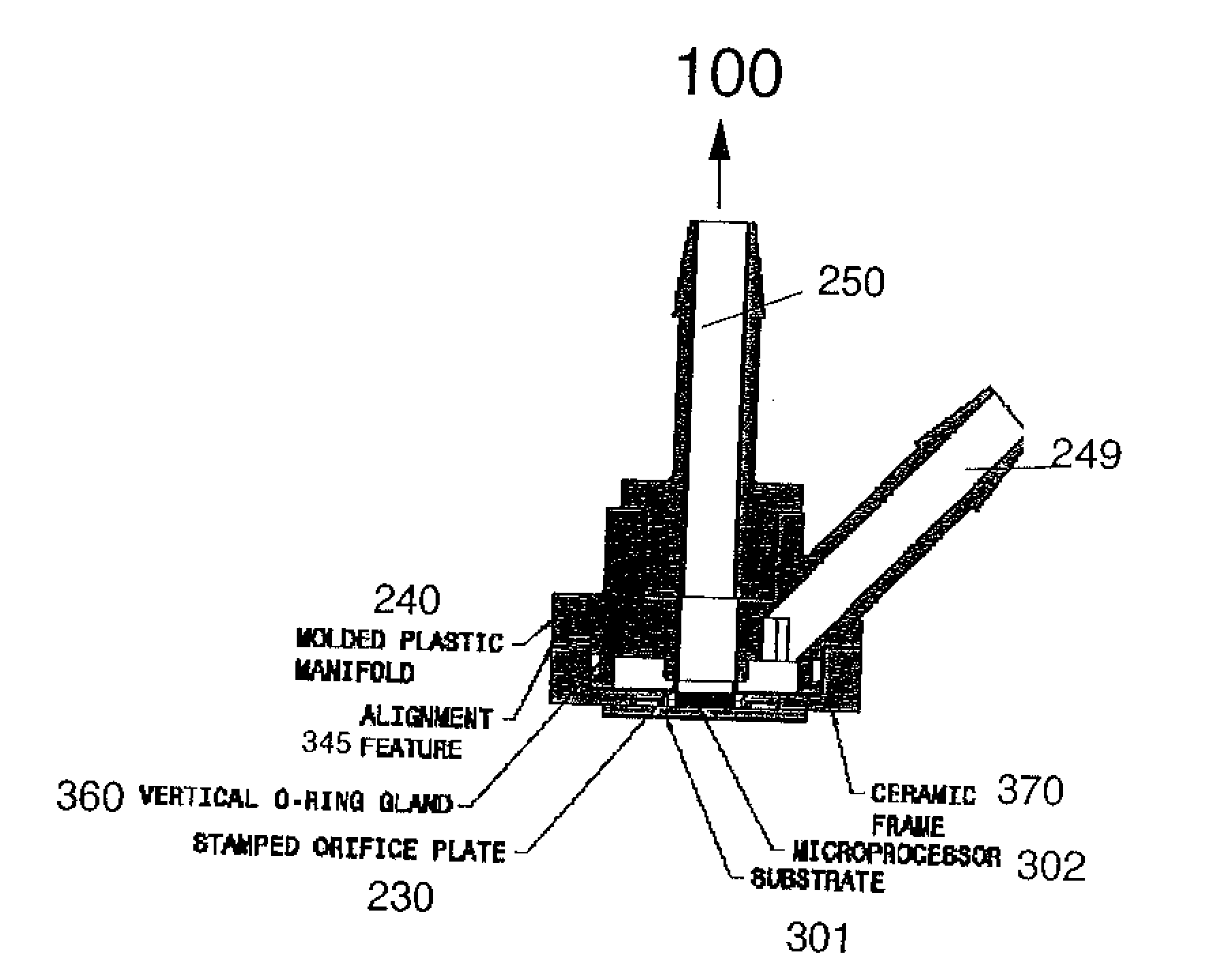
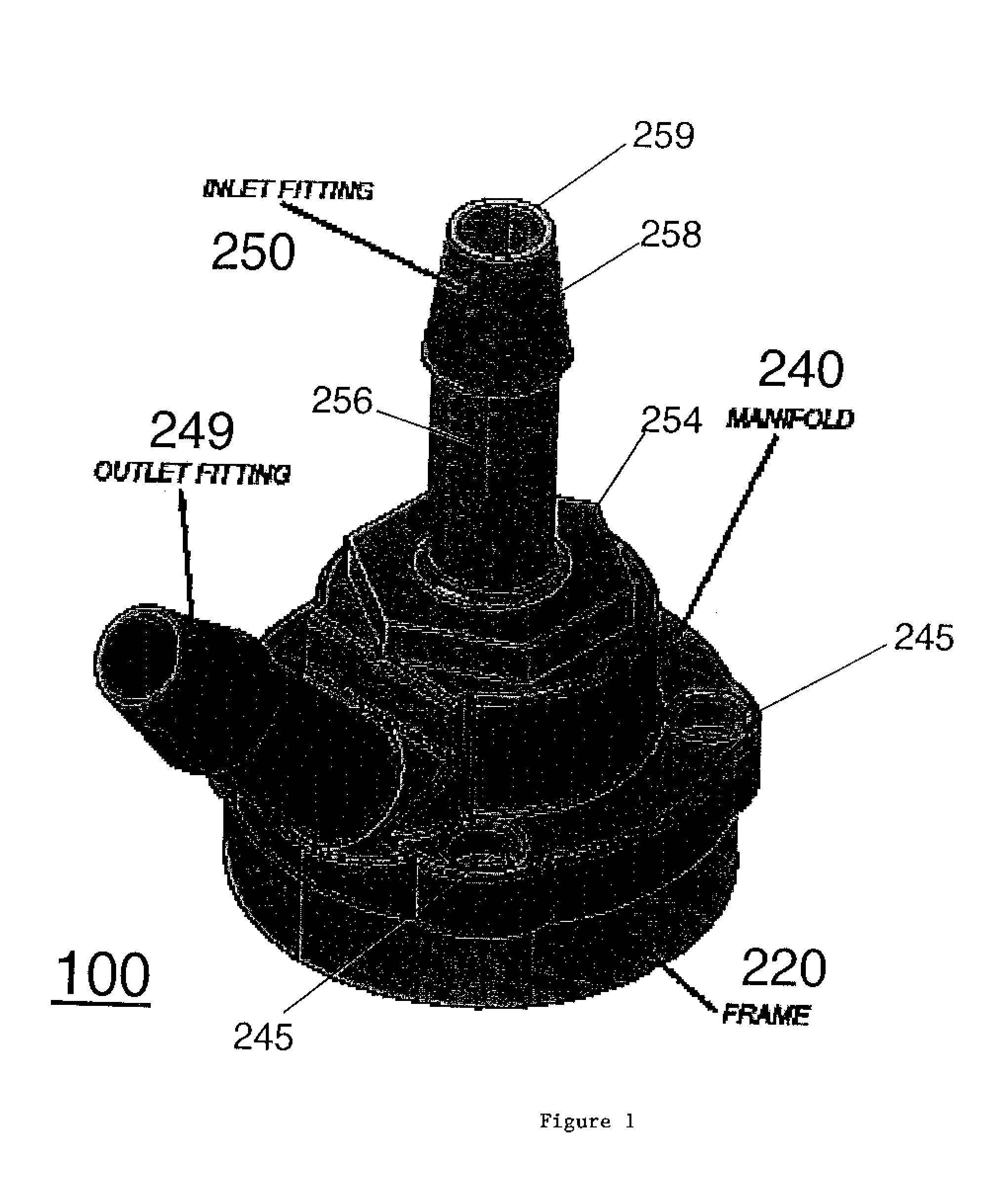
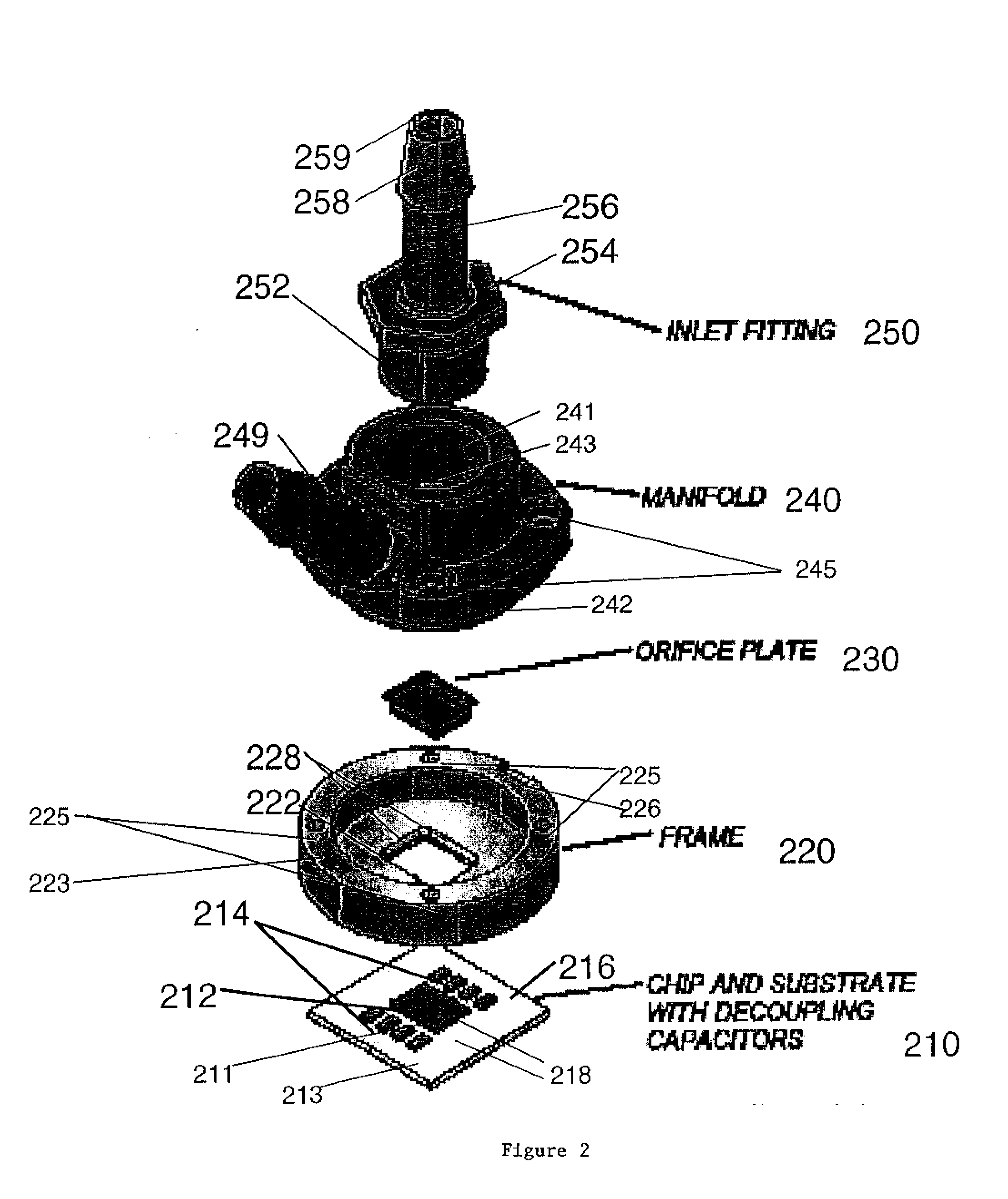
[0018]FIG. 1 provides for one embodiment of the present invention. In the embodiment illustrated in FIG. 1, a direct liquid jet impingement module 100 for high heat flux electronics packages is depicted. Liquid jet impingement cooling methods are a p...


PUM


Abstract

A direct liquid jet impingement module and associated method of providing such used in cooling of electronic components housed in an electronic package is provided. The module comprises a frame having an orifice to be placed over to-be-cooled components. A manifold is then disposed over the frame, such that the manifold opening is aligned with the frame orifice to ultimately enable fluid impingement on the to-be-cooled components. The manifold is formed to receive an inlet for the flow of coolants and an outlet fitting for removal of dissipated heat. A jet orifice plate is also provided inside the manifold opening, aligned with the frame orifice for directing fluid coolant flow over to-be-cooled components.

Description

CROSS-REFERENCE TO RELATED APPLICATIONS [0001] This application contains subject matter which is related to the subject matter of the following co-pending application, which is also assigned to the same assignee as this application, International Business Machines Corporation of Armonk, N.Y. The following application is hereby incorporated herein by reference in its entirety: Ser. No. 10 / 904,555 filed on Nov. 16, 2004, entitled “Fluidic Cooling Systems and Methods for Electronic Components” and assigned to the same assignee as this application.BACKGROUND OF THE INVENTION [0002] 1. Field of the Invention [0003] This invention relates to cooling of electronic packages in general and more particularly to cooling of electronic packages in a computing environment. [0004] 2. Description of Background [0005] The industry trend has been to continuously increase the number of electronic components inside computing system environments. Compactness allows for selective fabrication of smaller a...

Claims


Application Information

Patent Timeline
IPC IPC(8): H05K7/20
CPCH01L23/4735H01L2924/0002H01L2924/00
Inventor CAMPBELL, LEVICHOUDHARY, REHANELLSWORTH, MICHAELMARSTON, KENNETHTOY, HILTON
Owner IBM CORP
Learn More