Pump crosshead and connecting rod assembly

a crosshead and pump technology, applied in the direction of machines/engines, mechanical equipment, liquid fuel engines, etc., can solve the problems of pin failure, increased crosshead diameter, pin failure, etc., to reduce the bearing stress between the connecting rod and the crosshead, reduce the surface area, and reduce the bearing stress

Active Publication Date: 2008-01-10
FMC TECH INC
View PDF5 Cites 32 Cited by
  • Summary
  • Abstract
  • Description
  • Claims
  • Application Information

AI Technical Summary

Benefits of technology

[0012] Thus, the present invention provides a crosshead and connecting rod assembly which presents a relatively large surface area between these components for the discharge stroke of the pump and a smaller yet relatively l...

Problems solved by technology

However, the fact that the motion of the wrist pin relative to the bushing is oscillatory limits the ability of the bushing to develop a sufficient oil film for good lubrication.
However, this bushing is able to transfer the forces between the connecting rod and the crosshead only during the discharge stroke of the pump.
However, this requires the crosshead to be wider than the connecting rod bearing surface, which necessarily increases the crosshead diameter and, consequently, ...

Method used


Image

  • Pump crosshead and connecting rod assembly
  • Pump crosshead and connecting rod assembly
  • Pump crosshead and connecting rod assembly

Examples


Embodiment Construction

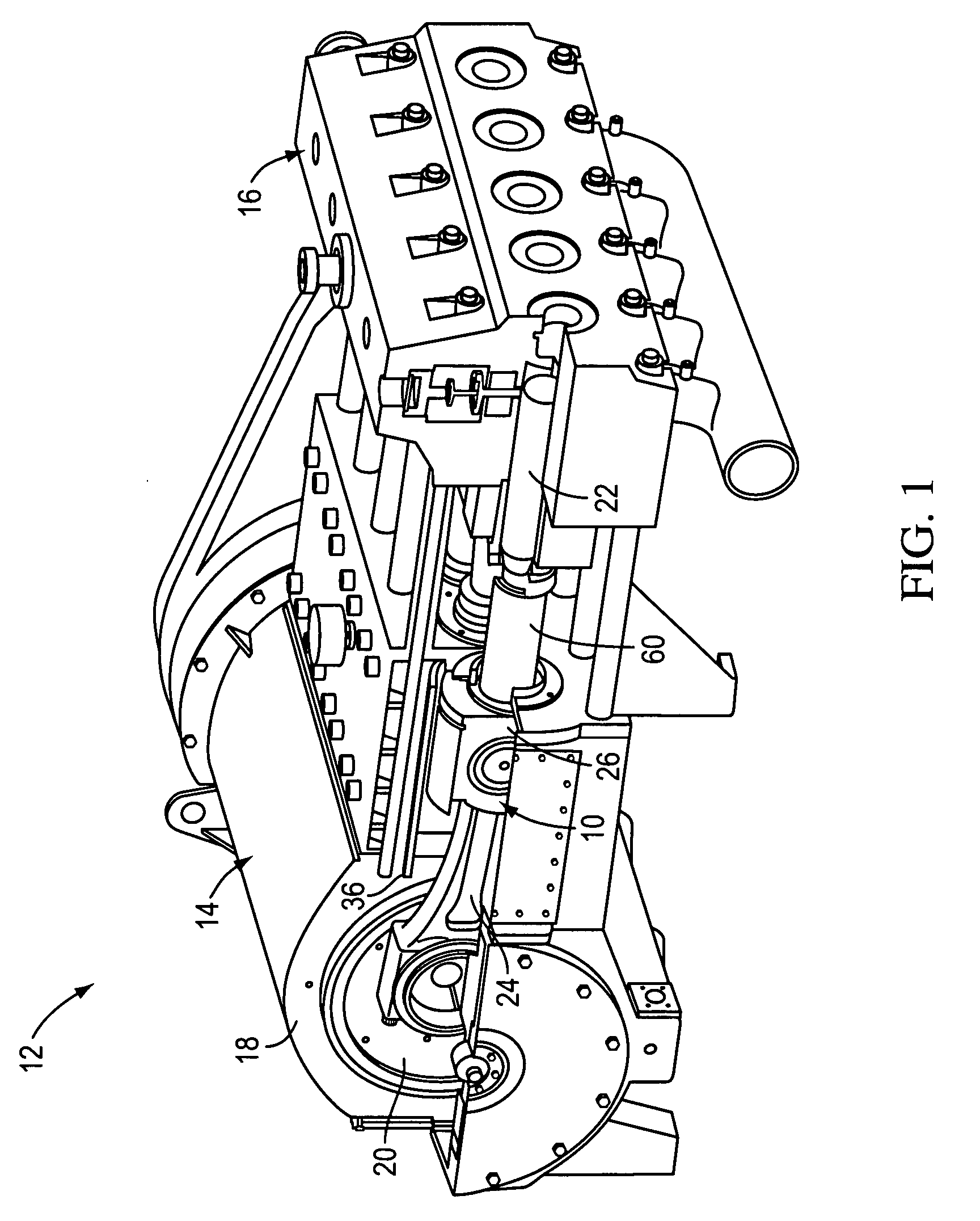
[0019] Referring to FIG. 1, the crosshead and connecting rod assembly of the present invention, which is indicated generally by reference number 10, is shown installed in an exemplary plunger pump 12. The pump 12 comprises a power end 14 for generating pumping power and a fluid end 16 for pumping a desired fluid. The power end 14 includes a gear reducer assembly 18 which is driven by a suitable motor (not shown), and a number of crankshafts 20 (only one of which is visible in FIG. 1) which are driven by the gear reducer assembly. The fluid end 16 includes a number of plungers 22, each of which is reciprocated within a corresponding plunger bore by a respective crankshaft 20.

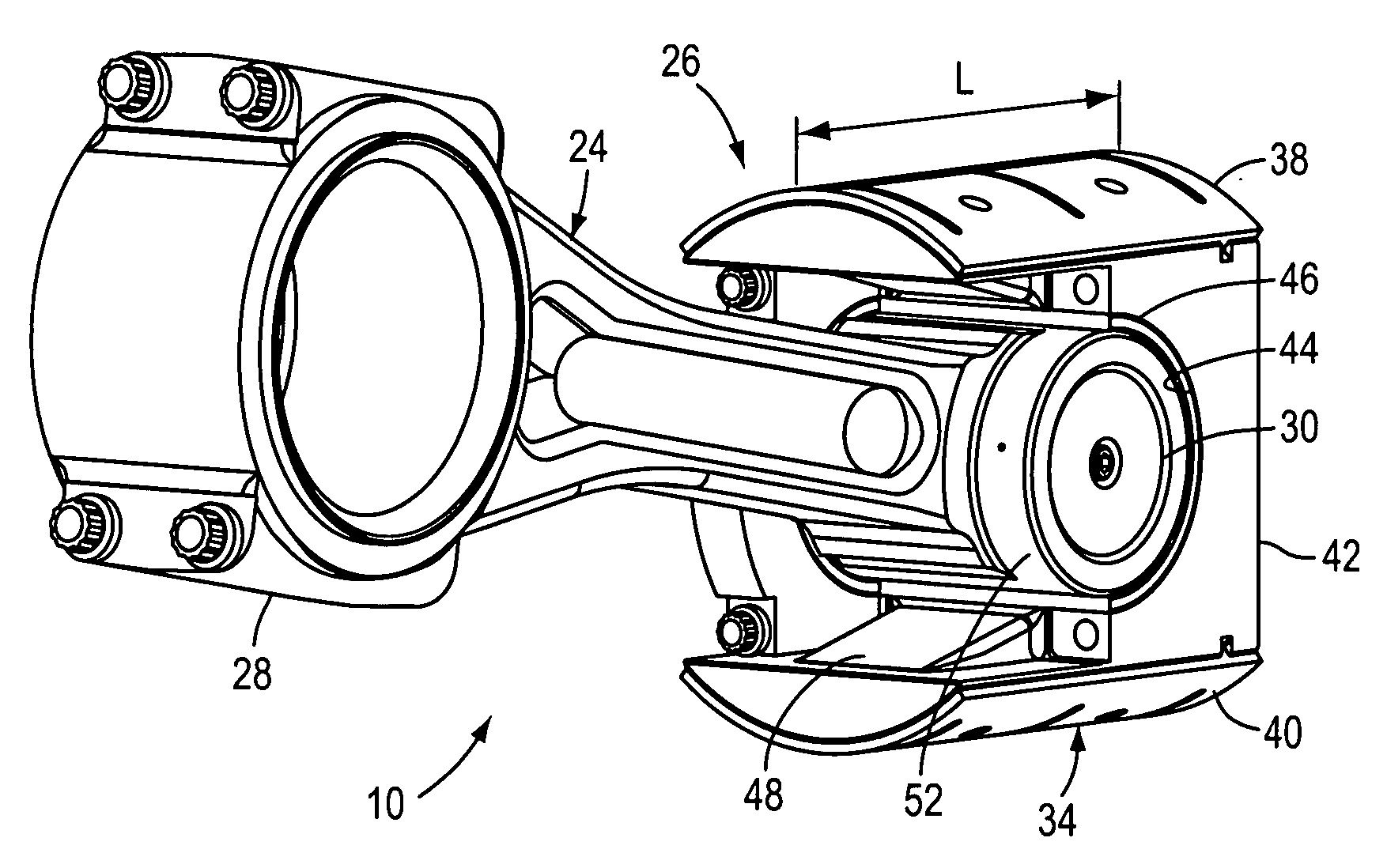
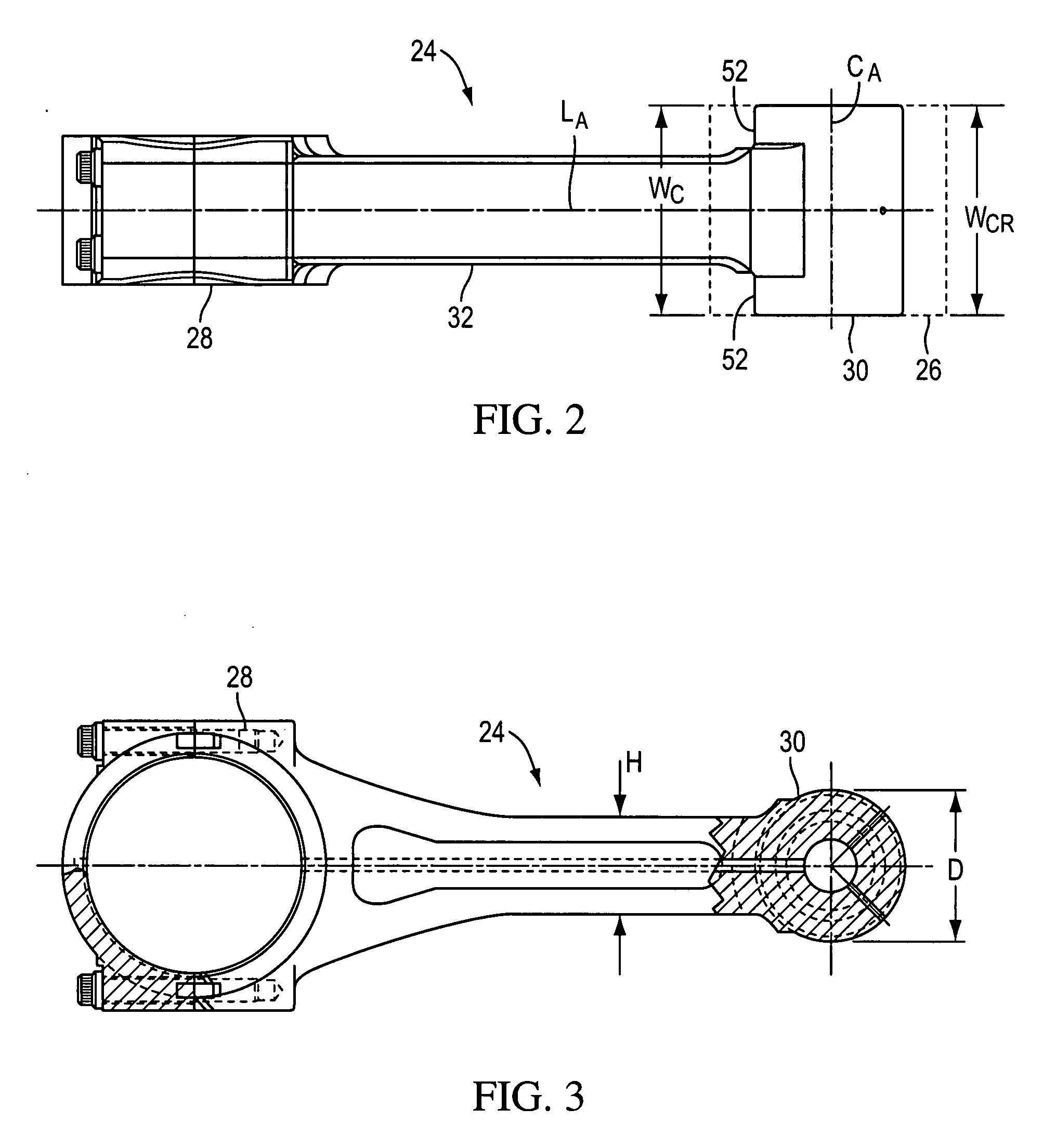
[0020] Each crankshaft 20 is connected to its corresponding plunger 22 by a crosshead and connecting rod assembly 10. As the name implies, each crosshead and connecting rod assembly 10 includes a connecting rod 24 and a crosshead 26. Referring also to FIGS. 2 and 3, the connecting rod 24 comprises first end 28 w...


PUM


Abstract

A crosshead and connecting rod assembly for a pump comprises a connecting rod which includes a first end that is rotatably connected to the crankshaft of the pump, a second end that comprises a generally cylindrical configuration, and a shaft that extends between the first and second ends. The second end comprises at least one annular shoulder adjacent to the shaft, and the crosshead and connecting rod assembly further comprises a crosshead which includes a body that comprises a generally semi-cylindrical socket within which the second end is rotatably received and at least one trunnion that comprises a generally semi-cylindrical recess which aligns with the socket and within which the shoulder is rotatably received when the trunnion is connected to the body.

Description

[0001] This application is based on and claims the benefit of U.S. Provisional Patent Application No. 60 / 816,992 filed on Jun. 27, 2006.BACKGROUND OF THE INVENTION [0002] The present invention relates to reciprocating plunger and piston-type pumps which are used, for example, in the well service industry. In particular, the invention relates to the connecting rod and crosshead assembly which converts the rotary motion generated at the power end of the pump into linear reciprocal motion which drives the plungers in the fluid end of the pump. [0003] Prior art reciprocating pumps for the well service industry include a crankshaft which generates rotary motion and a slider crank mechanism to convert this rotary motion into linear reciprocating motion. The crankshaft is connected to a slider, which is commonly called a crosshead, by means of a connecting rod. The connecting rod is coupled to the crosshead with some type of joint which allows force to be transferred between these componen...

Claims


Application Information

Patent Timeline
IPC IPC(8): F04B53/14F16C5/00F16J1/14
CPCF04B53/144F16C5/00F16J7/00F16C7/023
Inventor MCKELROY, RONDALL B.
Owner FMC TECH INC
Why Eureka
Try Eureka