
Continuous gain compensation and fast band selection in a multi-standard, multi-frequency synthesizer

a multi-frequency synthesizer and gain compensation technology, applied in the direction of oscillator generators, pulse automatic control, electrical equipment, etc., can solve the problems of data signal undetected shape or distortion, severe degrading system performance, methods may suffer limitations, etc., to facilitate the design of frequency synthesizers, reduce locking time, efficient and fast

Inactive Publication Date: 2008-01-10
TRIDEV RES
View PDF99 Cites 41 Cited by
  • Summary
  • Abstract
  • Description
  • Claims
  • Application Information

AI Technical Summary

Benefits of technology

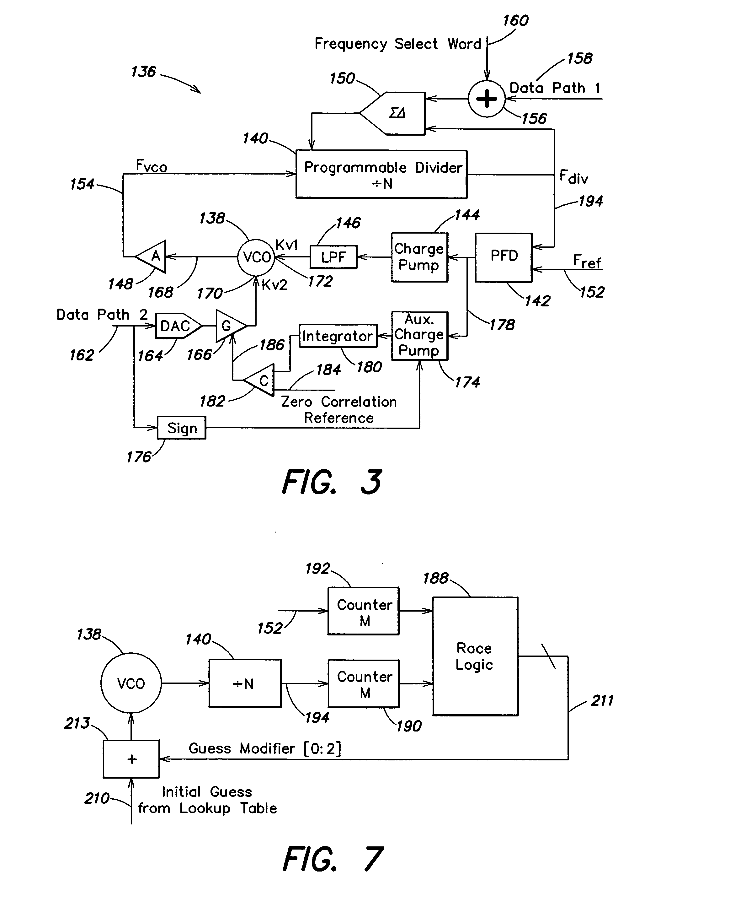
[0011]In one embodiment, there is provided a method for continuous gain compensation in a Two-Point Modulation frequency synthesizer that may involve no extra calibration sequences and may take advantage of the realization that all the information necessary for continually compensating the gain of the second data path may be already present in the system. In another embodiment, there may be provided a method for VCO band calibration which can reduce the locking time in half (compared to the 12.6 μs discussed above) by using predetermined initial settings for which bands should be used for which frequencies. In yet another embodiment, there may be provided a frequency synthesizer including a programmable divider with a very wide range of programmable division ratios. The programmable divider may be capable of operating at very high frequencies and at low power by interfacing directly to the VCO. In one example, a source-coupled logic approach may be used for the design of a cascaded chain of divider blocks that may allow for the use of a low power supply. These features may facilitate design of a frequency synthesizer that may be flexible (capable of synthesizing local oscillator carrier frequencies for a wide range of communication standards), efficient and fast.

Problems solved by technology

A problem with this approach is that the data is shaped in the frequency domain by the low-pass frequency response dynamics of the phase-locked loop.
If the bandwidth of the data signal is greater than the low-pass bandwidth of the loop, then the data signal will be undesirably shaped or distorted.
However, such methods may suffer from limitations imposed by the time that a system is allowed for a calibration update, since the process is disruptive to the actual operation of the frequency synthesizer and a phase lock must be reacquired after each calibration step.
These examples rely on the introduction of extraneous calibration sequences, and therefore suffer from the major disadvantage that the calibration sequences can introduce noise, or frequency spurs, into the frequency synthesizer, thereby severely degrading system performance.
Conventional frequency calibration approaches have the disadvantage in that they take too long to settle to a final selection of the appropriate band, particularly if the number of bands approaches 32 or even 64 (corresponding to a 5 or 6 bit VCO band control).

Method used


Image

  • Continuous gain compensation and fast band selection in a multi-standard, multi-frequency synthesizer
  • Continuous gain compensation and fast band selection in a multi-standard, multi-frequency synthesizer
  • Continuous gain compensation and fast band selection in a multi-standard, multi-frequency synthesizer

Examples


Embodiment Construction

[0030]According to aspects and embodiments of the invention, there is provided a frequency synthesizer capable of wideband operation and that may include a method of gain compensation that may not require external calibration sequences, as well as a method of fast VCO band selection. To facilitate wideband operation, embodiments of the frequency synthesizer may include switchable independent loop filters that may allow the frequency synthesizer to accommodate significant changes in bandwidth. In addition, there are disclosed methods of gain compensation and VCO band selection, as well as a fast, wideband programmable divider configuration that may be used in embodiments of frequency synthesizers according to the invention.

[0031]It is to be appreciated that this invention is not limited in its application to the details of construction and the arrangement of components set forth in the following description or illustrated in the drawings. The invention is capable of other embodiments...


PUM


Abstract

A frequency synthesizer capable of high speed, low power, wideband operation including a method of gain compensation, and a method of fast voltage controlled oscillator (VCO) band calibration. In addition, the frequency synthesizer may include two or more switchable independent loop filters to facilitate wideband operation. Such a frequency synthesizer may be used in many applications, and in one example, may be particularly suitable for use in a multi-band, multi-standard transmitter or radio transceiver.

Description

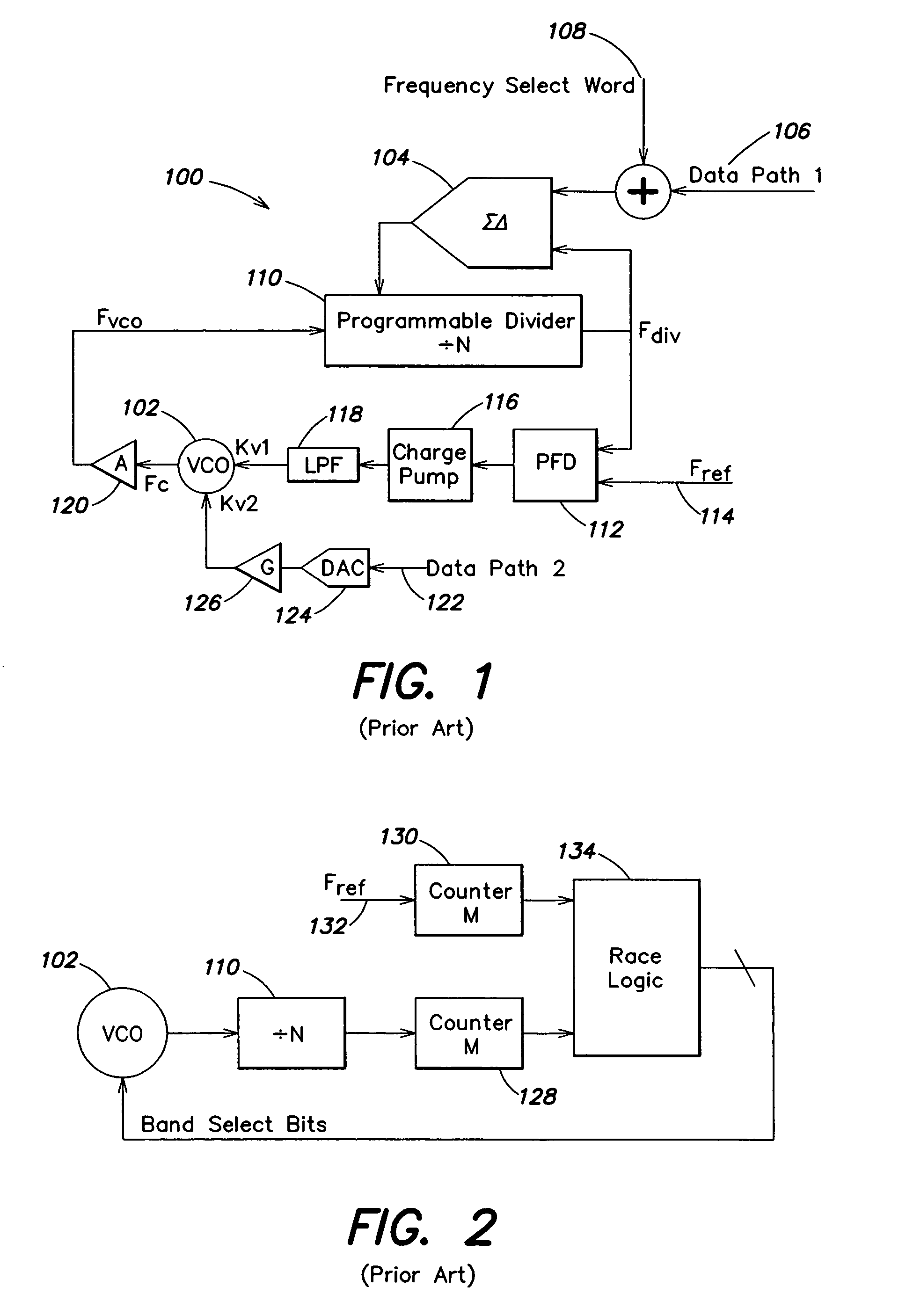
BACKGROUND[0001]1. Field of Invention[0002]The present invention is directed to a wideband, low power frequency synthesizer including gain compensation and operating frequency band selection and calibration.[0003]2. Discussion of Related Art[0004]In a wireless transmitter, a typical application for a frequency synthesizer is to provide a local oscillator signal (LO) to a mixer which in turn is used to up-convert a modulated data signal to a higher, radio frequency (RF), signal that is suitable for transmission over an antenna. If, as for example with the Global System Mobile (GSM) standard, a constant-envelope modulation is used, then the output of the frequency synthesizer can be directly modulated to superimpose modulated data on the voltage controlled oscillator (VCO) output. Referring to FIG. 1, there is illustrated an example of a conventional frequency synthesizer 100 including a VCO 102 in a phase-locked loop. The phase locked loop includes a programmable divider 110, a phase...

Claims


Application Information

Patent Timeline
Patent Type & Authority Applications(United States)
IPC IPC(8): H03B5/12
CPCH03C3/0925H03C3/0933H03C3/0941H03C3/0958H03L7/1976H03L7/0893H03L7/093H03L7/099H03L7/107H03C3/0991H03B5/1228H03B5/1212H03B5/1265H03B5/124H03L7/1072H03B2200/0072H03L7/187
Inventor VENUTI, JEFFBOHORQUEZ, JOSE
Owner TRIDEV RES
Learn More