Image pickup apparatus and method and apparatus for manufacturing the same

Inactive Publication Date: 2008-01-10
KYOCERA CORP
View PDF32 Cites 55 Cited by
  • Summary
  • Abstract
  • Description
  • Claims
  • Application Information

AI Technical Summary

Benefits of technology

[0015]According to one aspect of the present invention, the image pickup apparatus includes an element-including optical system, a detector, and a converter. The element-including optical system has an optical system and an optical wavefront modulation element which modulates an optical transfer function. The detector picks up an object image that passes through the optical system and the optical wavefront modulation element. The converter genera

Problems solved by technology

If the PSF varies, it becomes difficult to obtain an image with a large depth of field by convolution using a kernel.
In particular, in lens systems like zoom systems and autofocus (AF) systems, there is a large problem in adopting the above-mentioned structure because high precision is required in the optical design and costs are increased accordingly.
More specifically, in known image pickup apparatuses, a suitable convolution operation cannot be performed and the optical system must be designed so as to eliminate aberrations, such as astigmatism, coma aberration, and zoom chromatic aberration that cause a displacement of a spot image at wide angle and telephoto positions.
However,

Method used


Image

  • Image pickup apparatus and method and apparatus for manufacturing the same
  • Image pickup apparatus and method and apparatus for manufacturing the same
  • Image pickup apparatus and method and apparatus for manufacturing the same

Examples


Embodiment Construction

[0062]An embodiment of the present invention will be described below with reference to the accompanying drawings.

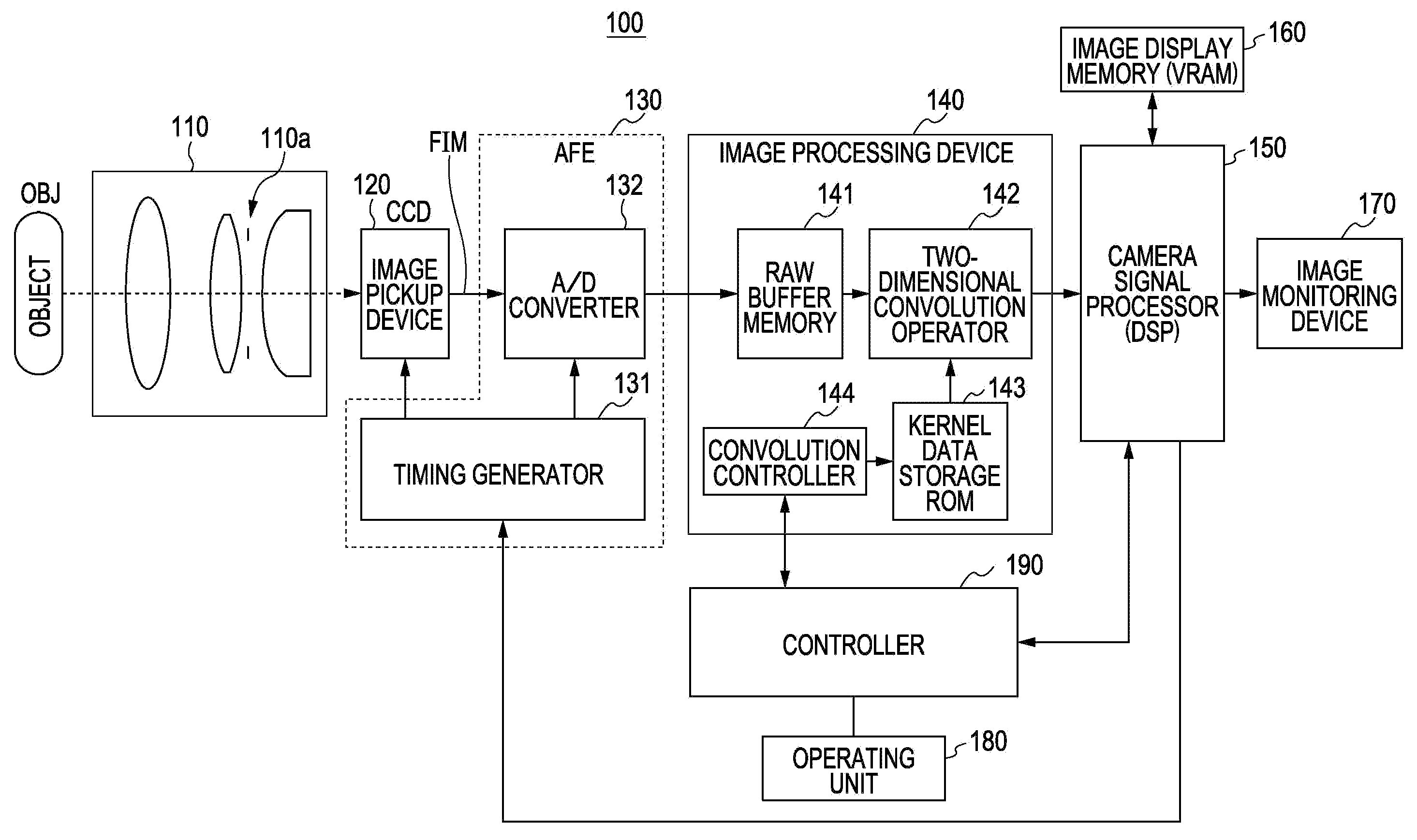
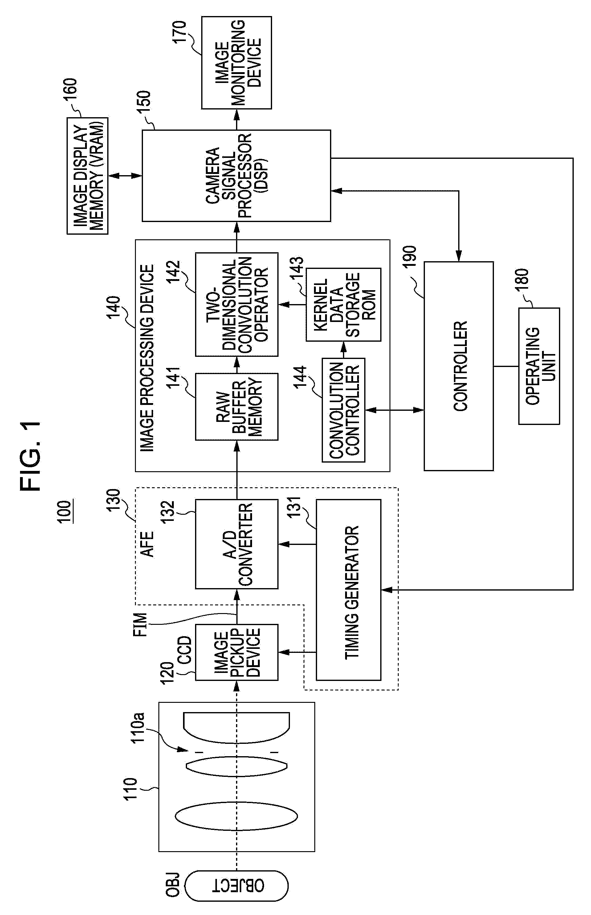
[0063]As shown in FIG. 1, an image pickup apparatus 100 according to the present embodiment includes an element-including optical system 110, a detector 120, an analog front end (AFE) unit 130, an image processing device 140, a signal processor (DSP) 150, an image display memory 160, an image monitoring device 170, an operating unit 180, and a controller 190.

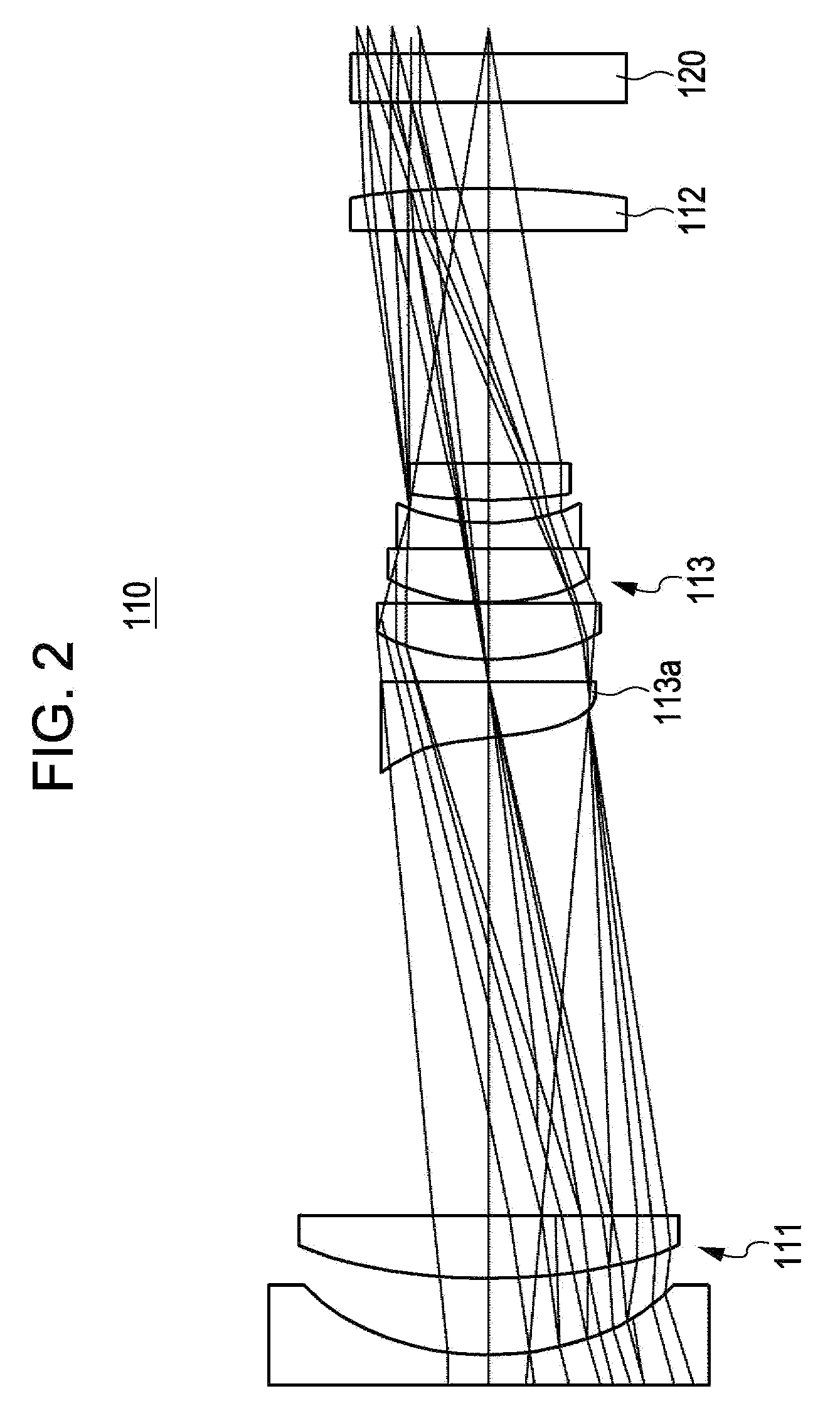
[0064]The element-including optical system 110 supplies an image obtained by shooting an object OBJ to the detector 120. The element-including optical system 110 includes a variable aperture 110a.

[0065]The detector 120 includes a CCD or a CMOS sensor. The detector 120 receives an image from the element-including optical system 110 and outputs first image information representing the image formed thereon. The output is sent to the image processing device 140 via the AFE unit 130 as a first image (FIM) electric signal....


PUM


Abstract

An image pickup apparatus includes an element-including optical system, a detector, and a converter. The element-including optical system has an optical system and an optical wavefront modulation element which modulates an optical transfer function. The detector picks up an object image that passes through the optical system and the optical wavefront modulation element. The converter generates an image signal with a smaller blur than that of a signal of a blurred object image output from the detector by performing a filtering process of the optical transfer function to improve a contrast. A focal position of the element-including optical system is set by moving the element-including optical system to the focal position which is corresponding to a predetermined object distance using a contrast of the object based on the image signal.

Description

CROSS-REFERENCE TO RELATED APPLICATIONS[0001]The present application claims priority under 35 U.S.C. §119 to Japanese Patent Application No. 2006-186025, filed Jul. 5, 2006 and is related to U.S. patent application Ser. No. 11 / 755,630, filed on May 30, 2007. The contents of each application are incorporated herein by reference in its entirety.BACKGROUND OF THE INVENTION[0002]1. Field of the Invention[0003]The present invention relates to an image pickup apparatus for use in a digital still camera, a mobile phone camera, a Personal Digital Assistant (PDA) camera, an image inspection apparatus, an industrial camera used for automatic control, etc., which includes a detector (what is called image pickup device, such as CCD and CMOS) and an optical system. The present invention also relates to a method and an apparatus for manufacturing the image pickup apparatus.[0004]2. Description of the Related Art[0005]Recently, as in digital cameras, solid-state detectors, such as Charge Coupled D...

Claims


Application Information

Patent Timeline
IPC IPC(8): H04N1/40
CPCG02B7/36
Inventor HAYASHI, YUSUKEOHARA, NAOTO
Owner KYOCERA CORP
Why Eureka
Try Eureka