Turbocharger with catalytic coating

a technology of catalytic coating and turbocharger, which is applied in the direction of machines/engines, stators, liquid fuel engines, etc., can solve the problems of affecting the efficiency of the compressor, and affecting the performance of the engin

Inactive Publication Date: 2008-01-17
ABB RES LTD
View PDF7 Cites 9 Cited by
  • Summary
  • Abstract
  • Description
  • Claims
  • Application Information

AI Technical Summary

Benefits of technology

[0008]Therefore, it is an object of the present invention to provide a compressor having a gas inlet housing and a compressor wheel, in which the flow-guiding parts are substantially kept clean in particular at high tempera

Problems solved by technology

If the dirty air also contains oil particles, the oil particles in particular become stuck on account of the low surface tension of oil.
As a result, the efficiency of the compressor can decrease by several percent within a short time.
This problem is encountered in particular in internal combustion engines wit

Method used


Image

  • Turbocharger with catalytic coating
  • Turbocharger with catalytic coating

Examples


Embodiment Construction

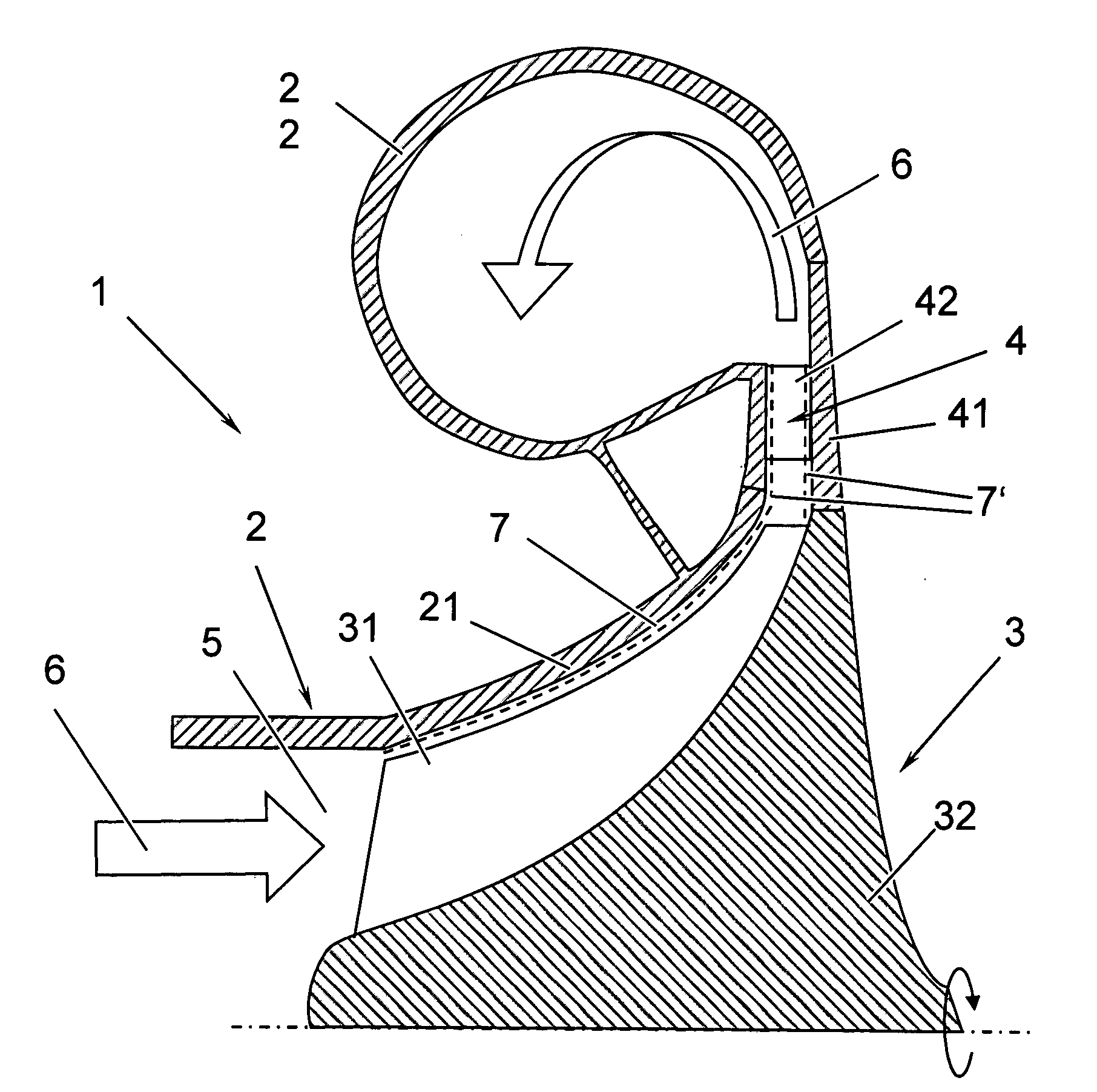
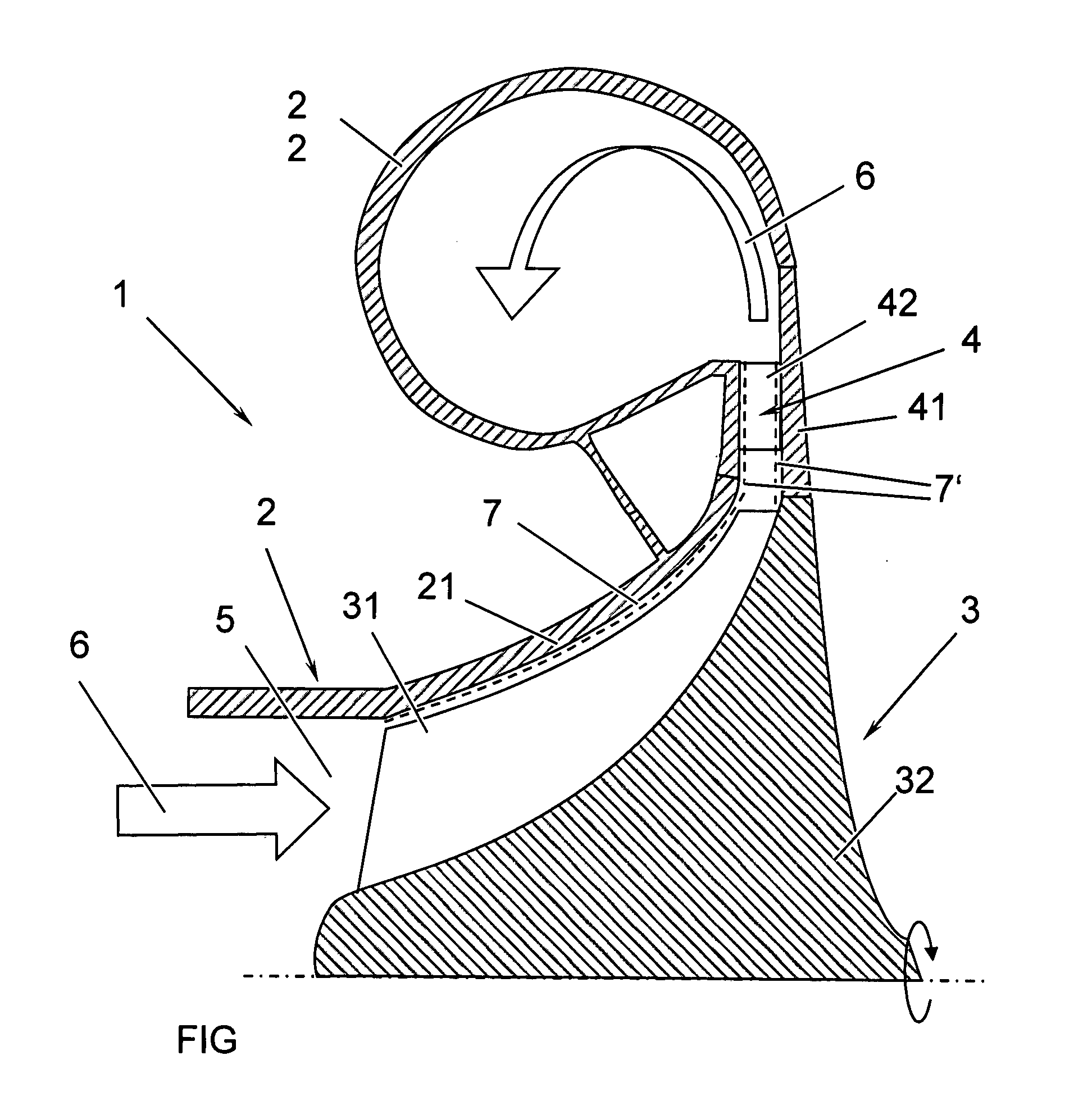
[0015]In the text which follows, the invention is explained on the basis of the example of a turbocharger, comprising a compressor 1 with a compressor wheel 3 and a gas inlet housing 2.

[0016]The FIGURE shows, in section along the machine axis of a turbocharger, a compressor-side excerpt from a turbocharger having a compressor 1. The compressor 1 has a gas inlet housing 2, a compressor wheel 3 which is mounted on a shaft (not shown in the FIGURE) and has rotor blades 31 and a hub 32, and a diffusor 4. A turbine wheel is likewise mounted on the shaft (not shown in the FIGURE). The gas inlet housing 2 has a housing inner side 21, which faces the medium that is to be compressed and along which the medium that is to be compressed flows. On the outside, a flow channel 5 is delimited by the housing inner side 21 of the gas inlet housing 2, and on the inside it is delimited by the hub 32 of the compressor wheel 3. The direction of flow of the medium 6 that is to be compressed runs along the...


PUM

PropertyMeasurementUnit
Surface roughnessaaaaaaaaaa

Abstract

A turbo machine having a rotor and a stator is at least partially provided on a flow-guiding part with a catalytic coating. The catalytic coating (7, 7′) comprises at least one oxide of a transition metal or an oxide of a mixture of transition metals, wherein the transition metals are elements from groups I B, in particular Cu, Ag, Ag, II B, in particular Zn, Cd, Hg, III B, in particular Sc, Y, IV B, in particular Ti, Zr, Hf, V B, in particular V, Nb, Ta, VI B, in particular Cr, Mo, W, VII B, in particular Mn, Tc, Re and/or VIII B, in particular Fe, Ru, Os, Co, Rh, Ir, Ni, Pd, Pt.

Description

FIELD OF THE INVENTION[0001]The invention relates to a compressor in accordance with the preamble of patent claim 1, to a turbocharger having a compressor of this type in accordance with the preamble of patent claim 9 and to a process for producing a compressor in accordance with the preamble of patent claim 10.BACKGROUND OF THE INVENTION[0002]It is nowadays common practice to use exhaust-gas turbochargers to boost the power of internal combustion engines. The exhaust-gas turbine of the turbocharger is acted on by the exhaust gases from the internal combustion engine, and the kinetic energy thereof is used for the induction and compression of air for the internal combustion engine. The compression increases the temperature and pressure of the air. As a result, temperatures of 180° C. or higher can occur at the guide vanes of the diffusor and the diffusor walls.[0003]The induction of dirty air can cause impurities to be deposited on that side of the gas inlet housing which faces the ...

Claims


Application Information

Patent Timeline
IPC IPC(8): F02B33/00B05D1/12
CPCF01D5/286F01D25/002F01N2510/00F02B39/00F05D2220/40F02C6/12F04D29/023F04D29/4206F02B39/16F05D2300/21F05D2300/611F05D2230/311F01D25/00F01D5/28F02B37/00
Inventor FUHRMANN, HENNINGTHIELE, MARTINAULETTA, TOMMASO
Owner ABB RES LTD
Why Eureka
Try Eureka