Insulator For A Wheel Suspension System

a technology of suspension system and insulator, which is applied in the field of insulators, can solve the problems of increasing the durability of insulators, so as to increase the durability and reliability of insulators, and increase the flexibility of insulators

Inactive Publication Date: 2008-01-17
BASF CORP
View PDF41 Cites 32 Cited by
  • Summary
  • Abstract
  • Description
  • Claims
  • Application Information

AI Technical Summary

Benefits of technology

[0010]The present invention is an insulator for a wheel suspension system of a vehicle. The suspension system includes a support structure adapted to be mounted to the vehicle, a piston rod disposed within the aperture and displaceable relative to the support structure along a line of travel, and a plate mounted to the piston rod. The insulator includes elastomeric material of a first density for compressible disposition between the support structure and the plate. The insulator presents an exterior surface for disposition adjacent at least one of the support structure and the plate. The exterior surface defines a channel extending into the elastomeric material for increasing the flexibility of the insulator when the support structure and the plate exert a compressive force on the insulator. The elastomeric material defines an increased density about the channel with the increased density greater than the first density for increasing the durability of the insulator about the channel when the support structure and the plate exert a compressive force on the insulator.
[0011]The present invention also includes a method of deforming an insulator with the use of a mold. The mold includes a first mold half having a protrusion. The method includes the steps of forming the insulator from a thermosetting, elastomeric microcellular polyurethane material and heating at least an exterior portion of the insulator to a first temperature. The method further includes the step of pressing the protrusion of the first mold half into the exterior portion of the insulator while maintaining the exterior portion of the insulator at the first temperature to simultaneously form a channel in the exterior portion of the insulator and permanently increase a density of the exterior portion of the insulator about the channel relative to a density of the remaining portions of the material.
[0012]Accordingly, the insulator has varying density such that the durability and reliability of the insulator is increased and the load and vibration absorption capability of the insulator is maintained. Specifically, the increased density about the channel limits the flexing of the insulator about the channel when the support structure and the plate exert compressive force on the insulator and the increased density strengthens the material about the channel. As such, the elastomeric material of the increased density reduces cracking about the channel to increase the durability and reliability of the insulator. In addition to the increased durability and reliability of the insulator, the insulator maintains load and vibration absorption capabilities because the elastomeric material of the first density advantageously absorbs loads and vibrations between the support structure and the plate.

Problems solved by technology

The insulator has a tendency to become cracked and / or cut as the insulator is repeatedly loaded and unloaded because the force delivered by the support structure and the plate to the insulator causes localized stress, i.e., concentrated stress, on the exterior surface of the insulator.
The cracks and / or cuts propagate with repeated loading and unloading of the insulator.
The cracks and / or cuts degrade the vibration dampening characteristics of the insulator and degrades the durability and reliability of the insulator.
However, as the support structure and the plate exert a compressive force on the insulator, the insulator flexes about the channel and cracks at a bottom of the channel.
However, increasing the density of the elastomeric material of the insulator disadvantageously limits the ability of the insulator to absorb loads and vibrations between the support structure and the plate.
In other words, the density of the entire insulator is increased, which limits the cracking about the channel but which also disadvantageously reduces the load and vibration absorption capabilities of the insulator.

Method used


Image

  • Insulator For A Wheel Suspension System
  • Insulator For A Wheel Suspension System
  • Insulator For A Wheel Suspension System

Examples


Embodiment Construction

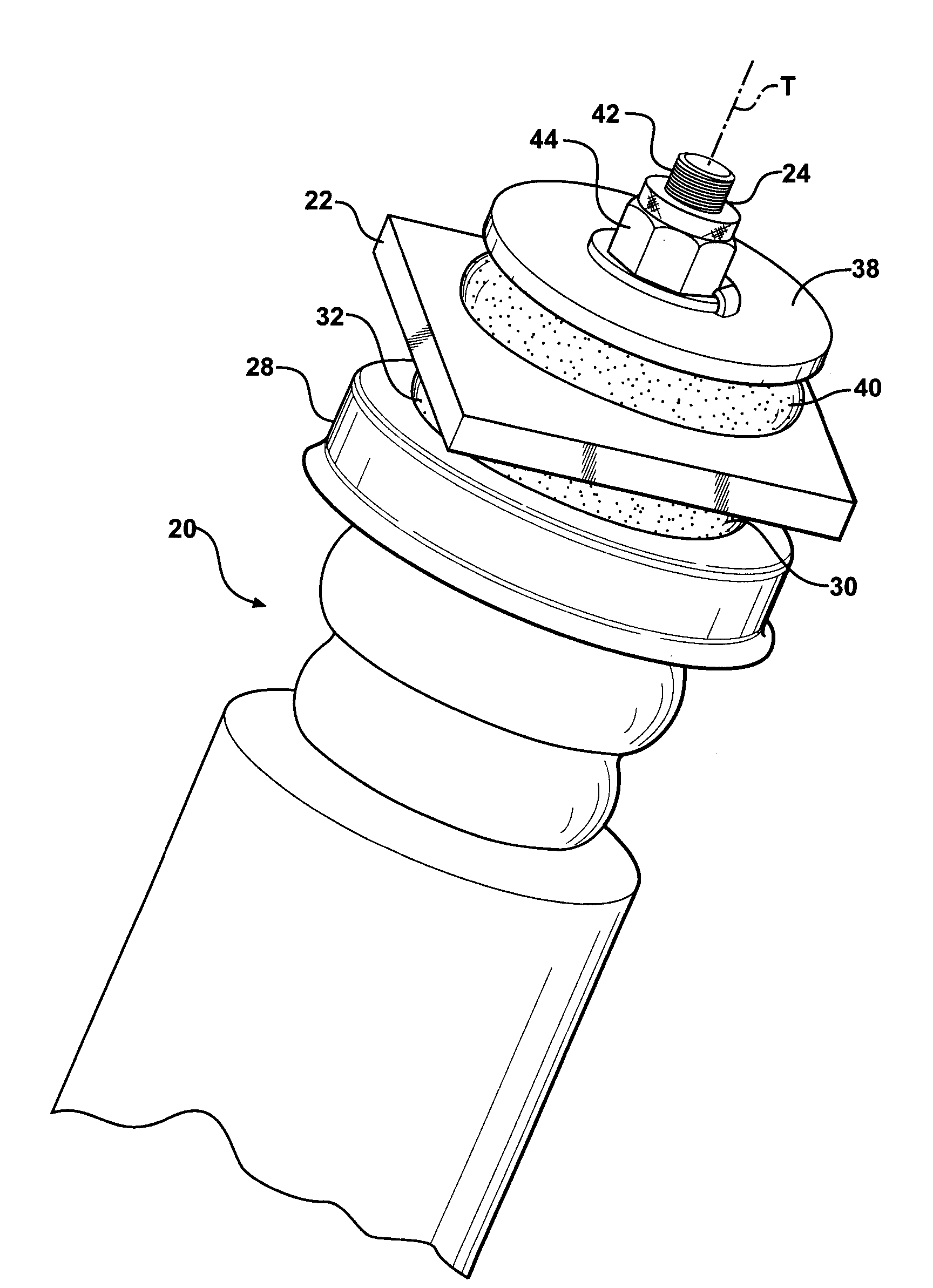
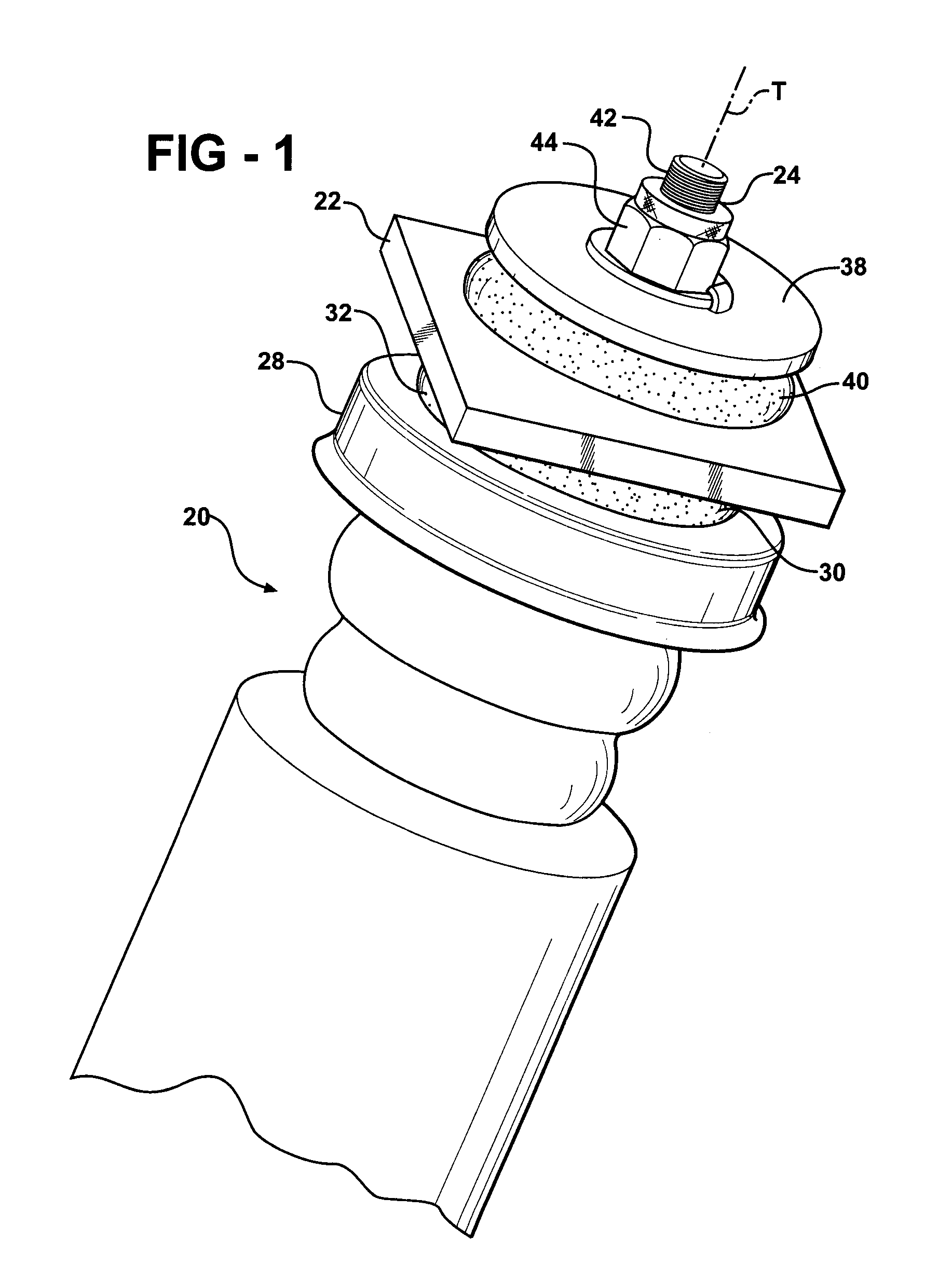
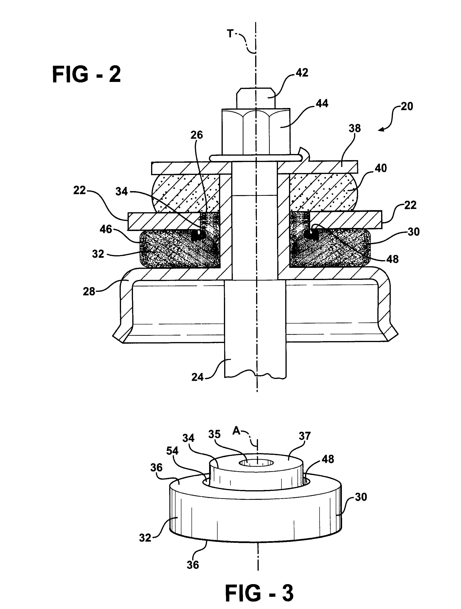
[0020]Referring to the Figures, wherein like numerals indicate corresponding parts throughout the several views, a wheel suspension system 20 for a vehicle is generally shown in FIGS. 1 and 2. The wheel suspension system 20 includes a support structure 22 adapted to be mounted to the vehicle. The wheel suspension system 20 further includes a piston rod 24 and the support structure 22 defines an aperture 26 with the piston rod 24 at least partially disposed within the aperture 26. A plate 28 is mounted to the piston rod 24. The piston rod 24 is displaceable relative to the support structure 22 along a line of travel T and the plate 28 moves relative to the support structure 22 during the displacement of the piston rod 24, i.e., the plate 28 is fixed to and moves with the piston rod 24. As appreciated by one skilled in the art, for example the piston rod 24 is displaced along the line of travel T when the vehicle travels over an uneven driving surface.

[0021]An insulator 30 is compress...


PUM

PropertyMeasurementUnit
temperatureaaaaaaaaaa

Abstract

An insulator for a wheel suspension system of a vehicle is formed of an elastomeric material. The elastomeric material defines a channel that provides increased flexibility to the insulator and defines an increased density about the channel that increases the durability of the insulator. The suspension system includes a support structure adapted to be mounted to the vehicle, a piston rod disposed within the aperture and displaceable relative to the support structure along a line of travel, and a plate mounted to the piston rod. The insulator is compressibly disposed between the support structure and the plate. The exterior channel increases the flexibility of the insulator to distribute localized stress on the insulator by the support structure and the plate. The increased density about the channel increases the durability of the insulator about the channel when the support structure and the plate exert a compressive force on the insulator.

Description

CROSS-REFERENCE TO RELATED APPLICATIONS[0001]The subject patent application claims priority to and all the benefits of U.S. Provisional Patent Application Ser. No. 60 / 807,518 which was filed on Jul. 17, 2006 and U.S. Provisional Patent Application Ser. No. 60 / 824,976 which was filed on Sep. 8, 2006, the entire specifications of both of which are expressly incorporated herein by reference.BACKGROUND OF THE INVENTION[0002]1. Field of the Invention[0003]The present invention relates to an insulator of varying density for a wheel suspension system. The present invention further includes a method of deforming the insulator to densify and to shape a portion of the insulator.[0004]2. Description of the Related Art[0005]A wheel suspension system for a vehicle includes a support structure having an aperture and adapted to be mounted to the vehicle. A piston rod of a damper tube or shock absorber is at least partially disposed within the aperture and is displaceable relative to the support st...

Claims


Application Information

Patent Timeline
Patent Type & Authority Applications(United States)
IPC IPC(8): B60G9/00B60G15/00B60G13/00
CPCB60G13/003Y10T16/05F16F9/54
Inventor DICKSON, DANIEL G.HUPRIKAR, ANAND
Owner BASF CORP
Why Eureka
Try Eureka