Actuator device, liquid-jet head and liquid-jet apparatus

a liquid jet head and actuator technology, applied in piezoelectric/electrostrictive/magnetostrictive devices, piezoelectric/electrostriction/magnetostriction machines, printing, etc., can solve the problems of low electrode, piezoelectric layer size, crystallinity degradation, etc., to improve the liquid jetting characteristic, driving stability and reliability.

Active Publication Date: 2008-01-17
SEIKO EPSON CORP
View PDF5 Cites 24 Cited by
  • Summary
  • Abstract
  • Description
  • Claims
  • Application Information

AI Technical Summary

Benefits of technology

[0014]The advantage of some aspects of the invention is to provide an actuator device, a liquid-jet head and a liquid-jet apparatus, each with an enhanced crystallinity of the piezoelectric layer, an enhanced driving durability and an enhanced reliability.

Problems solved by technology

This configuration causes a problem.
When such a way of forming the piezoelectric layer in which the piezoelectric layer is formed after patterning the lower electrode there are problems.
The crystal grain size of the piezoelectric layer (a dielectric material) becomes large, and degradation in crystallinity takes place as voids (air gaps) are formed.
Another problem is that no piezoelectric layer with a uniform film thickness is obtained because of the steps formed in the lower electrode.
Additionally, when the piezoelectric layer is formed through crystallization by baking, the lower electrode and the substrate (an elastic film), existing as base materials of the piezoelectric layer, cause an error in the heating temperature for heating the piezoelectric layer.
The error derives from the difference in the heat absorption between the substrate (the elastic film) and the lower electrode.
By such an error in the heating temperature, the crystallinity of the piezoelectric layer formed in regions facing the end portions of the lower electrode is degraded, and there arises a problem.
No piezoelectric layer with uniform crystallinity in a plane direction cannot be obtained.
Moreover, there arises a problem, due to these problems in manufacturing the piezoelectric layer, and due to the above-mentioned electric field concentration, when the piezoelectric elements are driven.
The configuration of JP-A-2000-263785, however, has a problem.
Consequently, there arises a problem.
The extension wiring provided from the upper electrode causes another problem.
It should be noted that these problems exist not only with a manufacturing method of an actuator device used for an ink-jet recording head, but also with a manufacturing method of an actuator device used for a liquid-jet head which ejects liquid other than ink.

Method used


Image

  • Actuator device, liquid-jet head and liquid-jet apparatus
  • Actuator device, liquid-jet head and liquid-jet apparatus
  • Actuator device, liquid-jet head and liquid-jet apparatus

Examples


embodiment 1

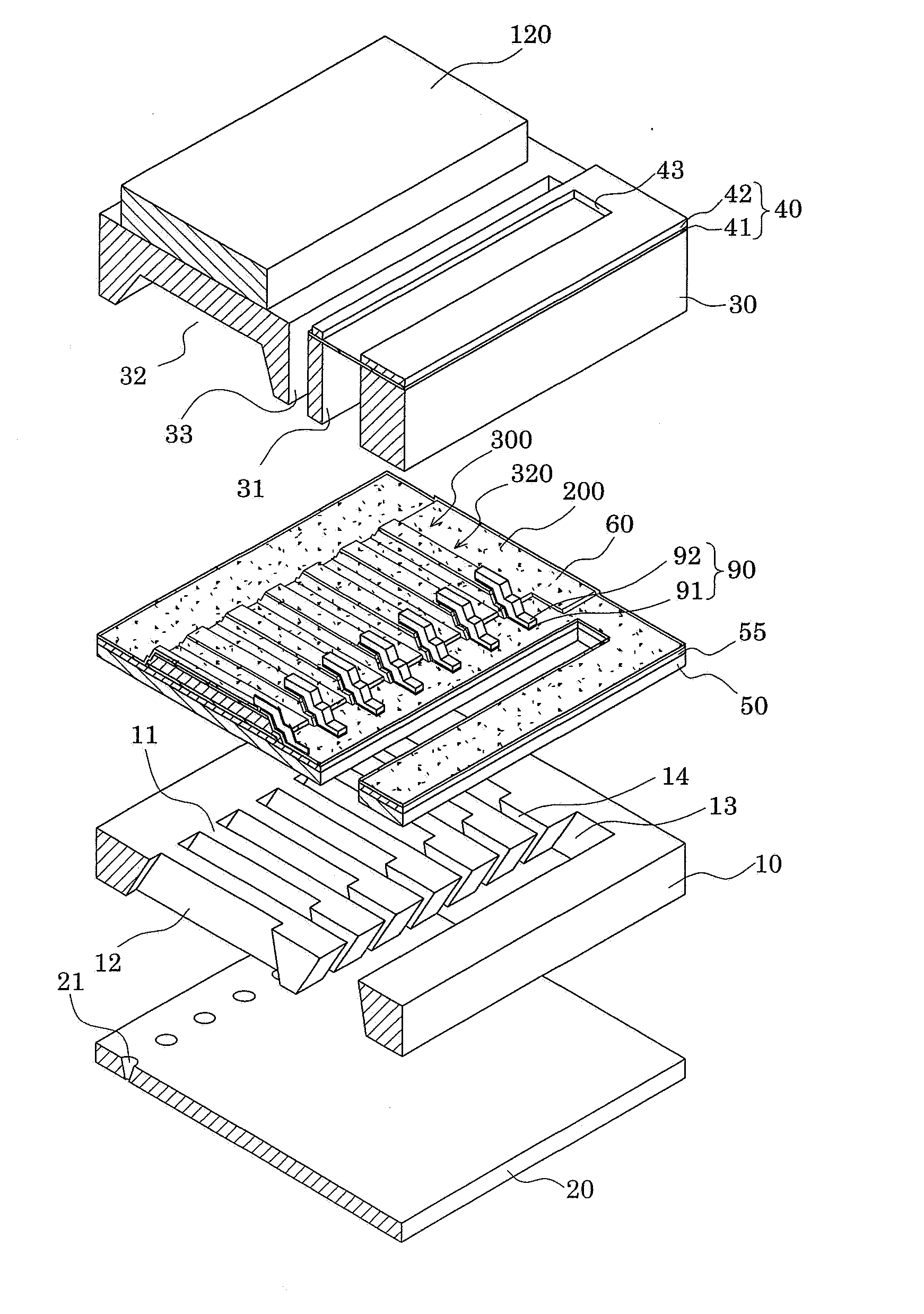
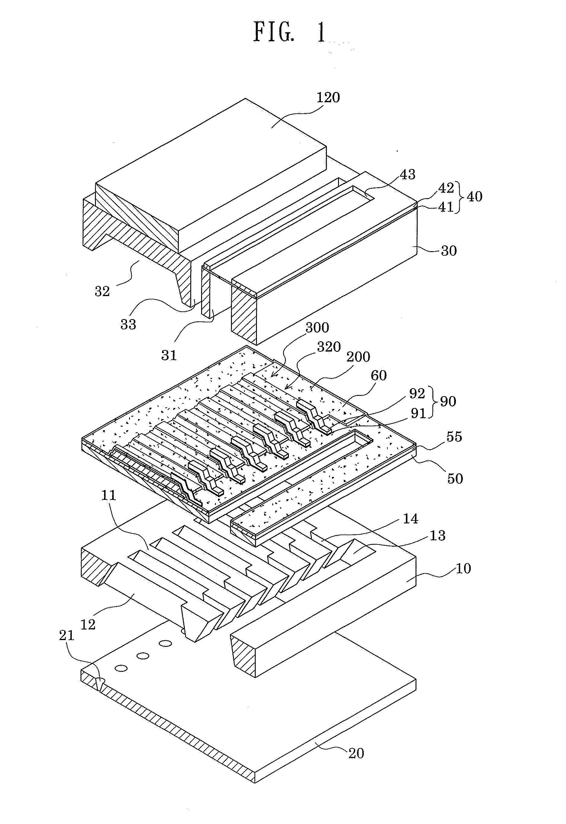
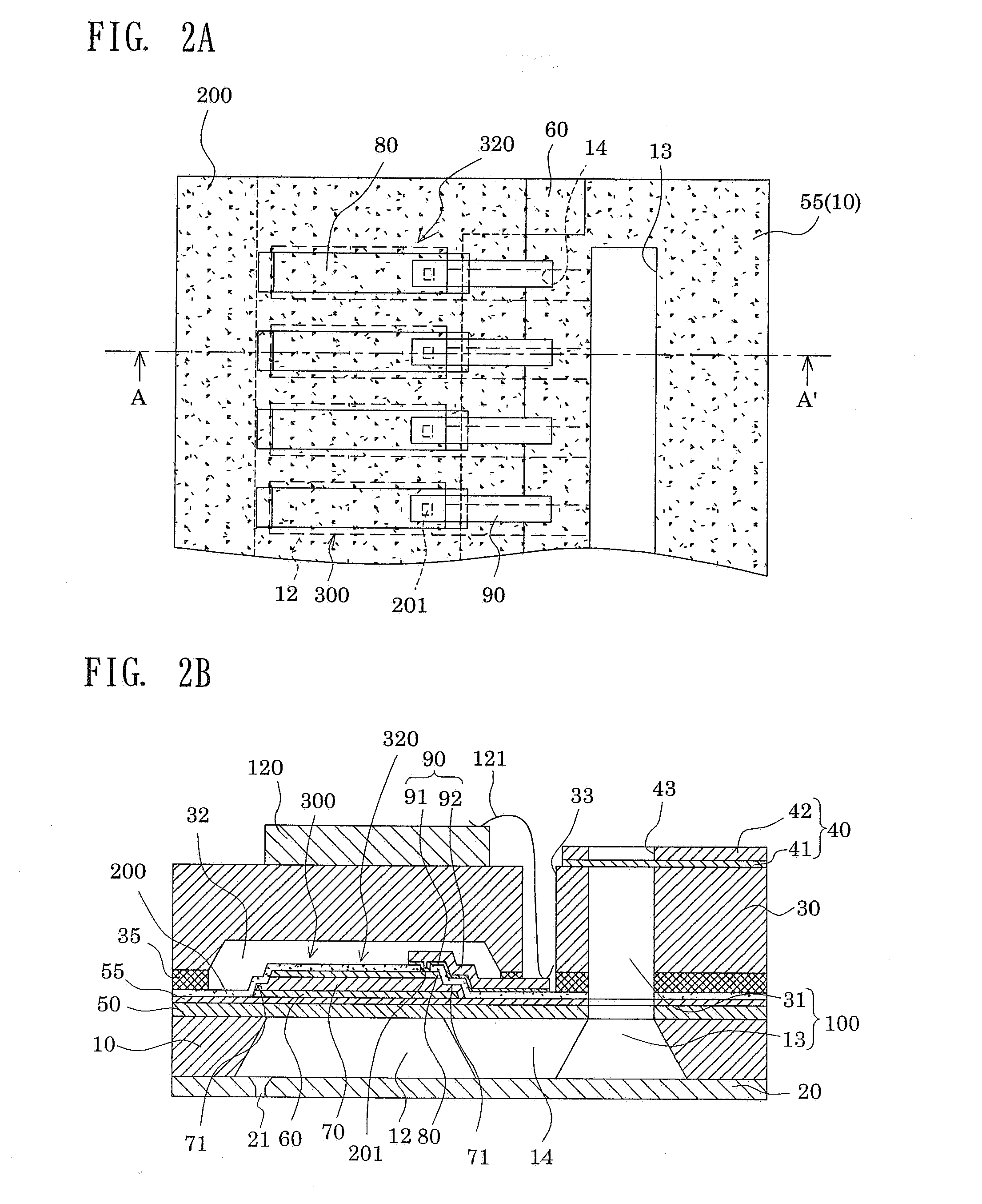
[0050]FIG. 1 is an exploded perspective view of an ink-jet recoding head, which is an example of a liquid-jet head according to Embodiment 1. FIGS. 2A and 2B are a plan view of a chief part, and a cross-sectional view taken along an A-A′ line in FIG. 2A, respectively, of the ink-jet recoding head according to Embodiment 1.

[0051]As shown in the drawings, a passage-forming substrate 10 is formed of a single-crystal silicon substrate in this embodiment. On one surface of the passage-forming substrate 10, an elastic film 50 made of silicon dioxide is previously formed by thermal oxidation in a thickness of 0.5 μm to 2 μm. On the passage-forming substrate 10, a plurality of pressure-generating chambers 12 partitioned by a plurality of compartment walls 11 are provided side by side in the width direction of each of the pressure-generating chambers 12. Additionally, in the passage-forming substrate 10, a communicating portion 13 is formed in a region outside the pressure-generating chamber...

examples 1 to 4

[0074]The piezoelectric elements having the above-described configurations were formed on the passage-forming substrate. The thicknesses of the thin film portions of the piezoelectric layers were set at 96.5%, 90.9%, 81.8% and 63.6% of the thickness (1.1 μm) of the piezoelectric layer in the regions to be the piezoelectric active portion. The piezoelectric elements thus prepared were referred to as Examples 1 to 4, respectively.

embodiment 2

[0105]FIGS. 8A and 8B are a cross-sectional view, and an enlarged view of a chief portion, respectively, of an ink-jet recoding head, which is an example of the liquid-jet head of the invention. Note that description will not be repeated by, instead, giving the same reference numerals to elements corresponding to those in FIG. 1.

[0106]As shown in FIGS. 8A and 8B, each of lead electrodes 90A is composed of an adhesive layer 91 and a metal layer 92A. The adhesive layer 91 extends to a region facing the corresponding ink supply path 14 from a region facing one end portion of the corresponding upper electrode film 80 on the protective film 200. Additionally, the metal layer 92A is provided, on the adhesive layer 91, in a region outside of a region facing the corresponding upper electrode film 80 on the adhesive layer 91. The region in which the metal layer 92A is provided is, in other words, a region outside of the corresponding piezoelectric active portion 320. Specifically, the metal ...


PUM


Abstract

Provided is an actuator device including piezoelectric elements which are displaceably provided on a substrate. Each piezoelectric element is formed of a lower electrode, a piezoelectric layer and an upper electrode. In the actuator device, longitudinal end portions of the upper electrode define longitudinal end portions of a piezoelectric active portion to be a substantial driver of the piezoelectric element. The lower electrode and the piezoelectric layer are provided continuously to the longitudinal outside of the piezoelectric active portion. Regions of the piezoelectric layer outside of the piezoelectric active portion are formed so that thin film portions may have a thin thickness.

Description

[0001]The entire disclosure of Japanese Patent Application No. 2006-177663 filed Jun. 28, 2006 is expressly incorporated by reference herein.BACKGROUND[0002]1. Technical Field[0003]The present invention relates to an actuator device including piezoelectric elements displaceably provided on a substrate. The invention also relates to a liquid-jet head and a liquid-jet apparatus provided with the actuator device as liquid jetting means for jetting liquid from nozzle orifices.[0004]2. Related Art[0005]As a piezoelectric element used for an actuator device, there is one constituted by interposing, between an upper electrode and a lower electrode, a piezoelectric layer made of a piezoelectric material exhibiting an electromechanical transduction function. An example of such piezoelectric materials is crystallized piezoelectric ceramic. Such an actuator device is generally called an actuator device of flexure vibration mode, and is used by being mounted on a liquid-jet head or the like. Re...

Claims


Application Information

Patent Timeline
Patent Type & Authority Applications(United States)
IPC IPC(8): B41J2/045H01L41/08H01L41/09B41J2/055B41J2/135B41J2/14B41J2/145H01L41/187H01L41/22H01L41/23H01L41/29H01L41/332
CPCH01L41/0973B41J2202/11B41J2/14233H10N30/2047
Inventor TAKAHASHI, TOMOAKI
Owner SEIKO EPSON CORP
Why Eureka
Try Eureka