
Method and apparatus for measuring the crepe of a moving sheet

Active Publication Date: 2008-01-17
HONEYWELL INT INC
View PDF51 Cites 50 Cited by
  • Summary
  • Abstract
  • Description
  • Claims
  • Application Information

AI Technical Summary

Benefits of technology

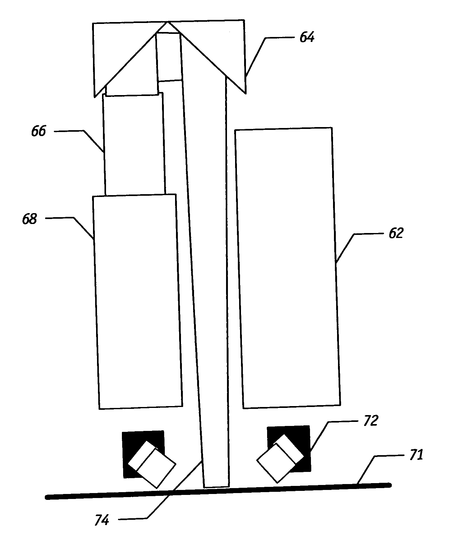
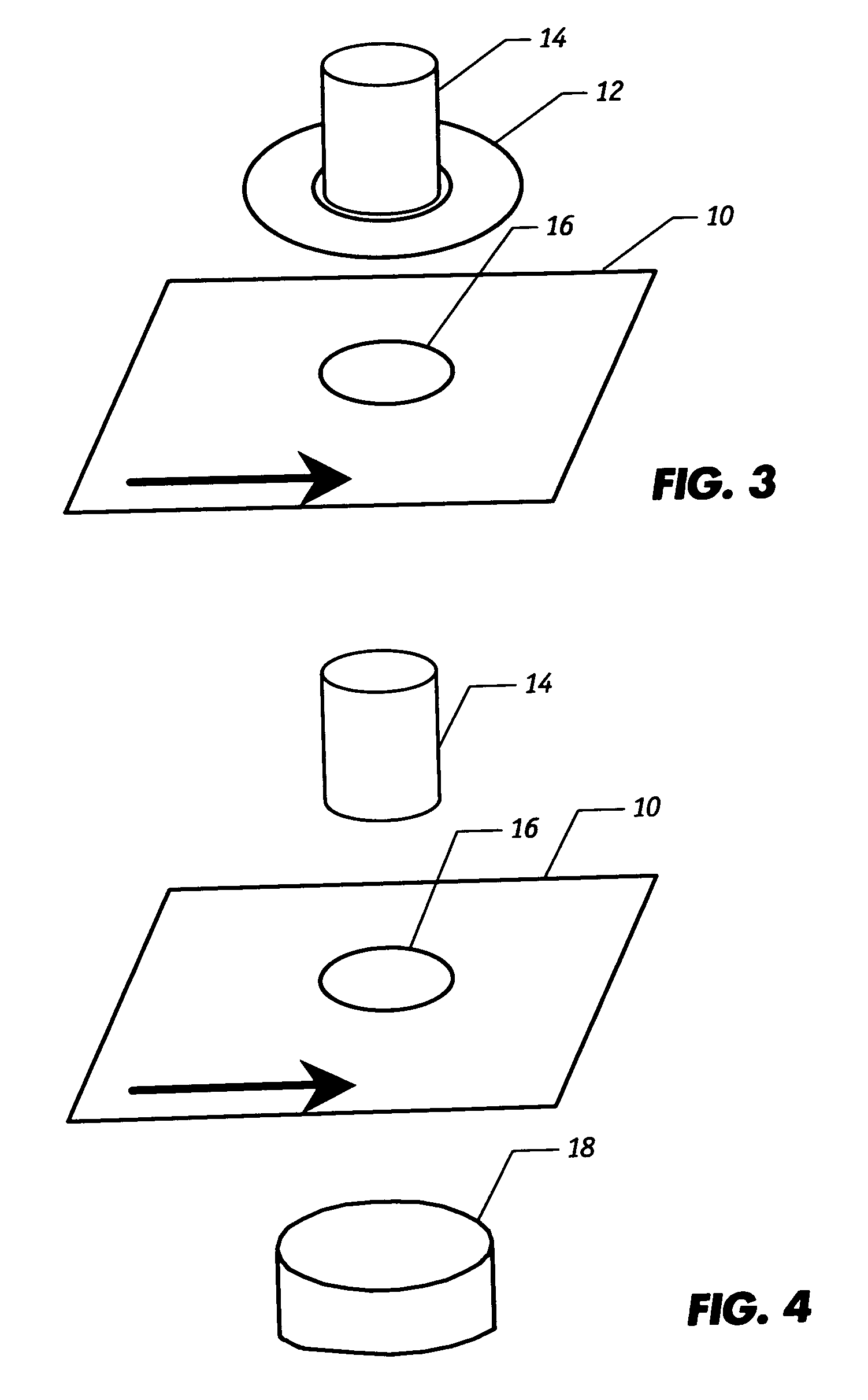
[0010]The present invention is based in part on the development of an image-based measurement technique that directly measures the crepe pattern orientation on a moving web that typically comprises non-woven material. The technique is capable of measuring a larger area of the web, e.g., paper, and thus produces a measurement which is more representative of the web. The invention is particularly suited for measuring the crepe structure of tissue during the manufacturing operation. A suitable arrangement of illumination, optical elements, and an imaging device obtain images of the tissue surface. The image resolution is sufficient to represent tissue crepe folds at the scale of the crepe. A spectral analysis of some or of all the images reveals the crepe folding pitch. Further analysis of the image optionally reveals other crepe structural parameters, such as the distribution of crepe fold orientation angles and distribution of linear fold lengths. Thus, changes in the crepe structure can be detected promptly, allowing corrective actions to be taken in a timely manner. Corrective actions can include (i) changing the doctor blade, (ii) adjustment of doctor blade angle, and (iii) adjustment of application of additives to the Yankee surface. Some corrective actions can be taken by a suitable control system which takes the crepe measurement as an input. The present invention provides a solution for measuring the crepe pitch and other crepe pattern parameters of a moving tissue web without the shortcomings of prior art.

Problems solved by technology

Deviations in crepe pattern either locally or across the whole sheet can indicate a range of process problems, such as excessive wear on the doctor blade, or improper flow of additives to the Yankee cylinder.
However, in this mode of operation, the device requires that the tissue path be confined to a very narrow plane by a sheet stabilizer in the immediate vicinity where detection is made, which is problematic.
In any of these scenarios, the force applied can easily lead to decreping or even to web disruption, since most grades of tissue are not strong, and the crepe folds are only weakly bonded.
The forces involved also increase nonlinearly with the speed of the web, thereby exacerbating the difficulty at the high speeds of modern tissue machines.
At present, there is no known method to measure the crepe structure until a sample can be taken from a finished reel to the laboratory for analysis.
This leads to delays between the occurrence of a product quality disturbance or process defect and its detection.
Thus remedial actions are delayed and considerable quantities of unacceptable tissue may be produced.

Method used


Image

  • Method and apparatus for measuring the crepe of a moving sheet
  • Method and apparatus for measuring the crepe of a moving sheet
  • Method and apparatus for measuring the crepe of a moving sheet

Examples


Embodiment Construction

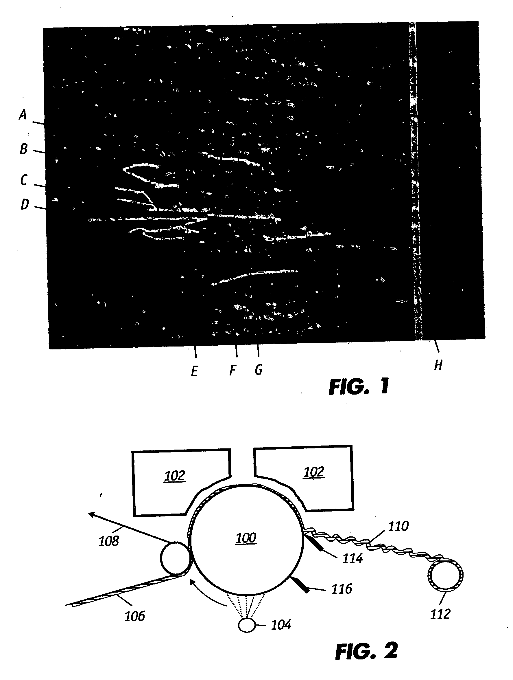
[0043]The present invention relates to methods and devices for directly measuring the crepe pattern and related structures or features on the surface of a moving sheet or web product such as tissue during the manufacturing operation. FIG. 2 illustrates a typical tissue creping process whereby non-creped sheet 106 is conveyed by a continuous felt line 108 to the surface of a rotating Yankee drying cylinder 100. Dryer hoods 102 apply heat that is directed to the upper or hood side surface of the sheet. The addition of an adhesive material from a spray boom 104 onto the cylinder surface helps keep sheet 106 adhered to the cylinder. The sheet becomes creped sheet 110 as it is scraped off the cylinder surface by the doctor blade 114. The cleaning blade 116 removes excess materials from the surface. The crepe pattern of creped sheet 110 can be monitored by positioning the inventive measuring apparatus between the Yankee cylinder 100 and reel 112. The crepe pattern on the creped sheet 110 ...


PUM


Abstract

An image-based measurement technique that directly measures the crepe pattern on a moving sheet employs a suitable arrangement of illumination, optical elements, and an imaging device to obtain digital images of the sheet surface. The image resolution is sufficient to represent tissue crepe folds at the scale of the crepe. A spectral analysis of some or of all the images reveals the crepe folding pitch. Further analysis of the image optionally reveals other crepe structural parameters, such as the distribution of crepe fold orientation angles and distribution of linear fold lengths. Corrective actions can be implemented in response to changes in the crepe structure. The pitch of creping is the primary parameter for describing the crepe pattern; in addition, analyzing the images with a gradient operator can yield information regarding the orientation of the crepe folds and distribution of angles of the crepe furrows on the hood side or equivalently of the crepe seams on the cylinder side.

Description

FIELD OF THE INVENTION[0001]The present invention is directed to techniques of determining the spatial structure properties on webs and particularly to image-based measurements of the crepe structures on paper by on-line image analysis.BACKGROUND OF THE INVENTION[0002]In the manufacture of paper on continuous papermaking machines, a web of paper is formed from an aqueous suspension of fibers (stock) on a traveling mesh, papermaking fabric, or wire and water drains by gravity and suction through the fabric. The web is then transferred to the pressing section where more water is removed by pressure and vacuum. The web next enters the dryer section where steam heated dryers and hot air completes the drying process. The paper machine is, in essence, a water removal, system. A typical forming section of a papermaking machine includes an endless traveling papermaking fabric or wire, which travels over a series of water removal elements such as table rolls, foils, vacuum foils, and suction...

Claims


Application Information

Patent Timeline
IPC IPC(8): D21F11/00
CPCG01B11/306G01N21/89G06T2207/30124G01N2021/8681G06T7/001G01N33/346
Inventor SHAKESPEARE, JOHN F.
Owner HONEYWELL INT INC
Learn More