Turbo pneumatic cylinder of pneumatic tool

Inactive Publication Date: 2008-01-17
GISON MASCH CO LTD
View PDF1 Cites 3 Cited by
  • Summary
  • Abstract
  • Description
  • Claims
  • Application Information

AI Technical Summary

Benefits of technology

[0004]It is therefore a primary object of the present invention to provide a

Problems solved by technology

The turbo pneumatic cylinder can output a certain power, however, when the airflow flows within the conventional turbo pneumatic cylinder, the kinetic energy is not effectively increased.
Therefore, the output power

Method used


Image

  • Turbo pneumatic cylinder of pneumatic tool
  • Turbo pneumatic cylinder of pneumatic tool
  • Turbo pneumatic cylinder of pneumatic tool

Examples


Embodiment Construction

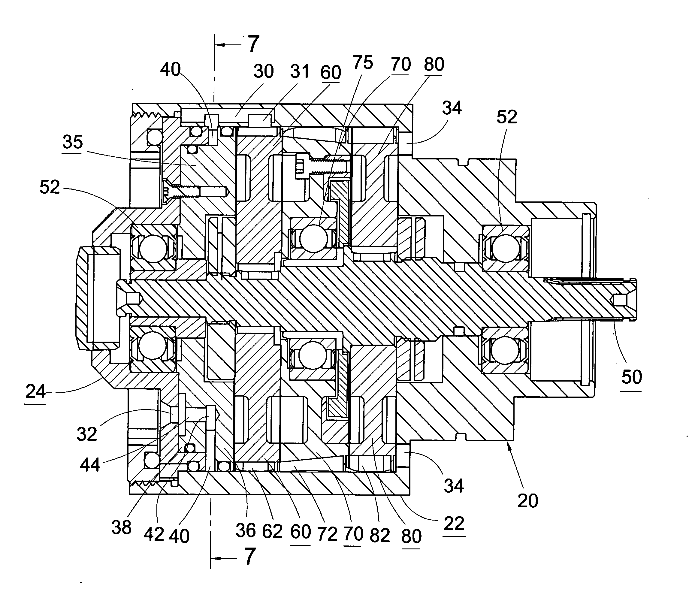
[0016]Please refer to FIGS. 1, 4 and 6. A preferred embodiment of the turbo pneumatic cylinder 10 of the present invention includes a cylinder housing 20, two turbines 60, 80 and a one-way rotatable inverse turbine 70 disposed in the cylinder housing 20.

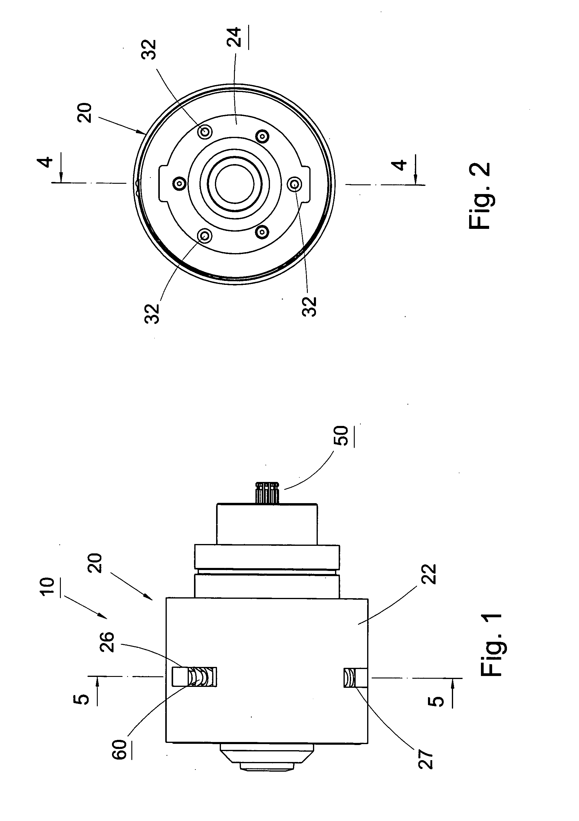
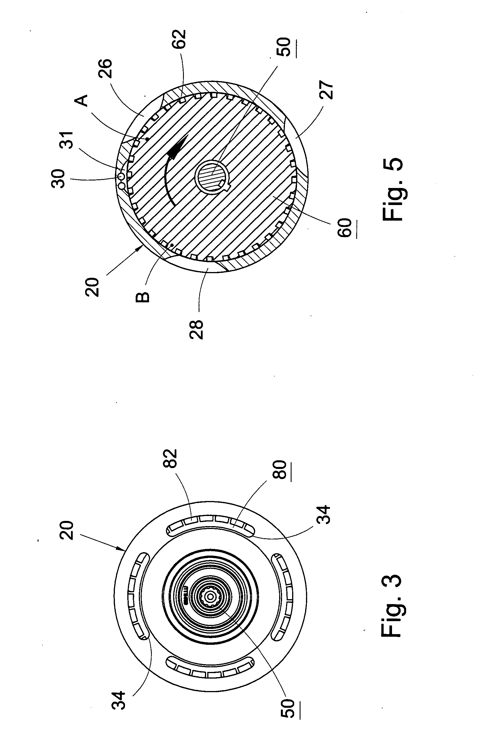
[0017]The cylinder housing 20 is composed of a cylinder body 22 and a cylinder cap 24 plugged in a front end of the cylinder body 22. A cylinder chamber 25 is formed in the cylinder housing 20. A wall of the cylinder body 22 is formed with an intake 26 and two exhaust ports 27, 28 for communicating the cylinder chamber 25 with outer side. Preferably, the intake 26 and the exhaust ports 27, 28 are positioned on the same circumference of the cylinder body 22. An inner face of the wall of the cylinder chamber 25 is formed with a flow way 30 between the intake 26 and the exhaust port 28. In this embodiment, the flow way is composed of two axial channels. The end of the flow way 30 is formed with a crescent guide opening 31 as shown in FI...


PUM


Abstract

A turbo pneumatic cylinder of a pneumatic tool, including a front turbine, a one-way rotatable inverse turbine and a rear turbine. The front and rear turbines are mounted on the rotary shaft of the pneumatic cylinder. The inverse turbine is one-way rotatably fitted on the rotary shaft between the front and rear turbines. Multiple blades are arranged on the circumferences of the front and rear turbine and the inverse turbines. The blades of the inverse turbine are directed in a direction reverse to the direction of the blades of the front and rear turbines. The front and rear turbines and the rotary shaft rotate in the same direction, while the inverse turbine rotates in a direction reverse to the direction of the front and rear turbines. As a result, the efficiency of the pneumatic cylinder is enhanced and the twisting of the pneumatic cylinder is avoided when it is in operation.

Description

BACKGROUND OF THE INVENTION[0001]The present invention is related to a pneumatic tool, and more particularly to a turbo pneumatic cylinder of a pneumatic tool, which can output maximum torque at lowest gas consumption.[0002]High-pressure gas serves as the power source of a pneumatic tool, and drives a pneumatic cylinder to operate the pneumatic tool. In a conventional turbo pneumatic cylinder, after the high-pressure gas flows into the pneumatic cylinder, the high-pressure gas simply drives the turbine to rotate and then is exhausted from the pneumatic cylinder. The turbo pneumatic cylinder can output a certain power, however, when the airflow flows within the conventional turbo pneumatic cylinder, the kinetic energy is not effectively increased. Therefore, the output power is limited. Also, the gas consumption of the conventional turbo pneumatic cylinder is great so that a considerable amount of energy is waste.[0003]Furthermore, when the turbine of the turbo pneumatic cylinder ope...

Claims


Application Information

Patent Timeline
IPC IPC(8): F03D1/02
CPCY02E10/72F03D9/00Y10S415/904F01D1/26
Inventor LIN, FREDDY
Owner GISON MASCH CO LTD
Why Eureka
Try Eureka