Luminescent materials that emit light in the visible range or the near infrared range

a technology of luminescent materials and visible ranges, applied in the field of luminescent materials, can solve the problems of limited effectiveness in preventing counterfeiting, and achieve the effects of high quantum efficiency, narrow spectral width, and convenient processing

Inactive Publication Date: 2008-01-17
OMNIPV
View PDF13 Cites 66 Cited by
  • Summary
  • Abstract
  • Description
  • Claims
  • Application Information

AI Technical Summary

Benefits of technology

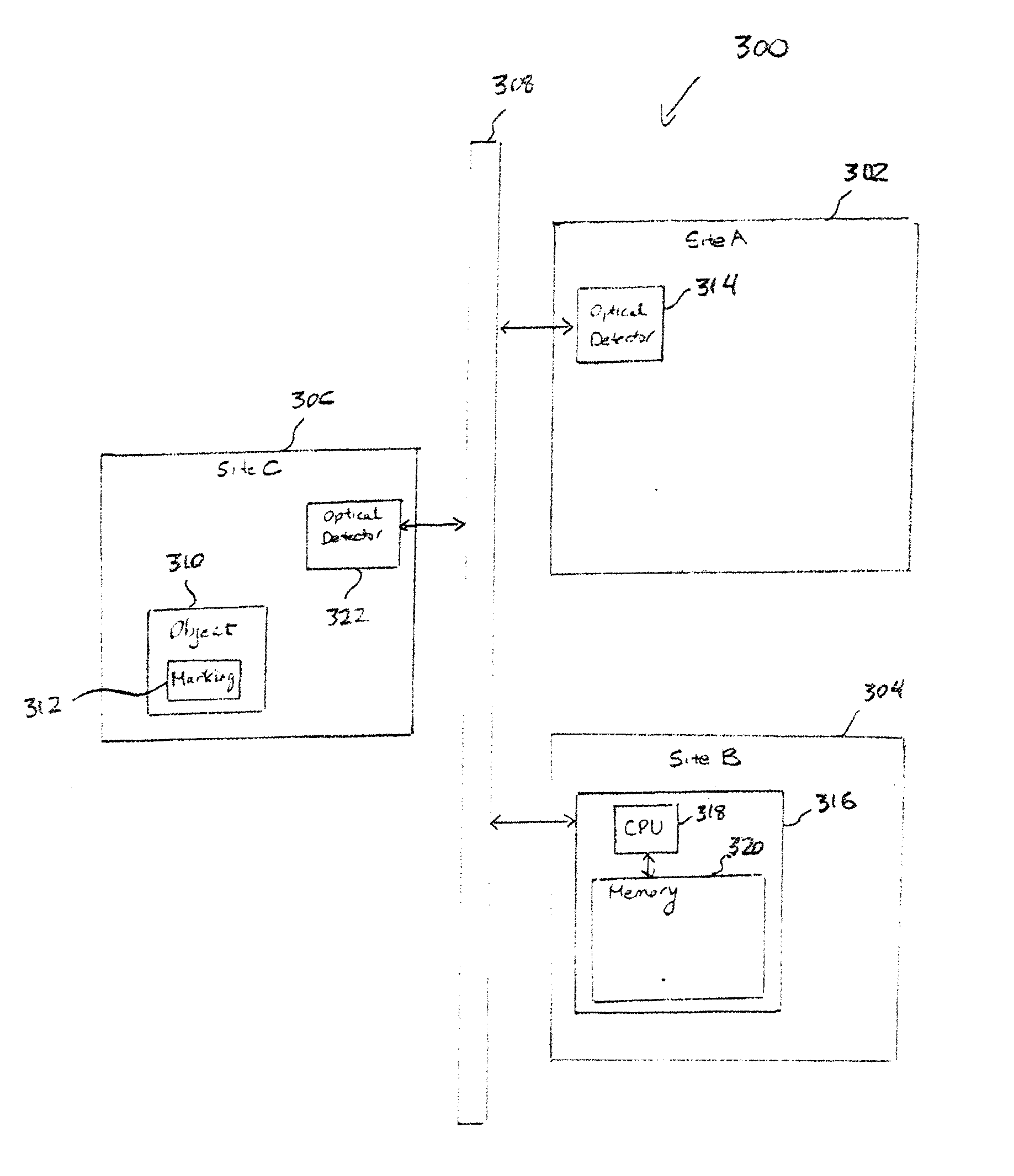
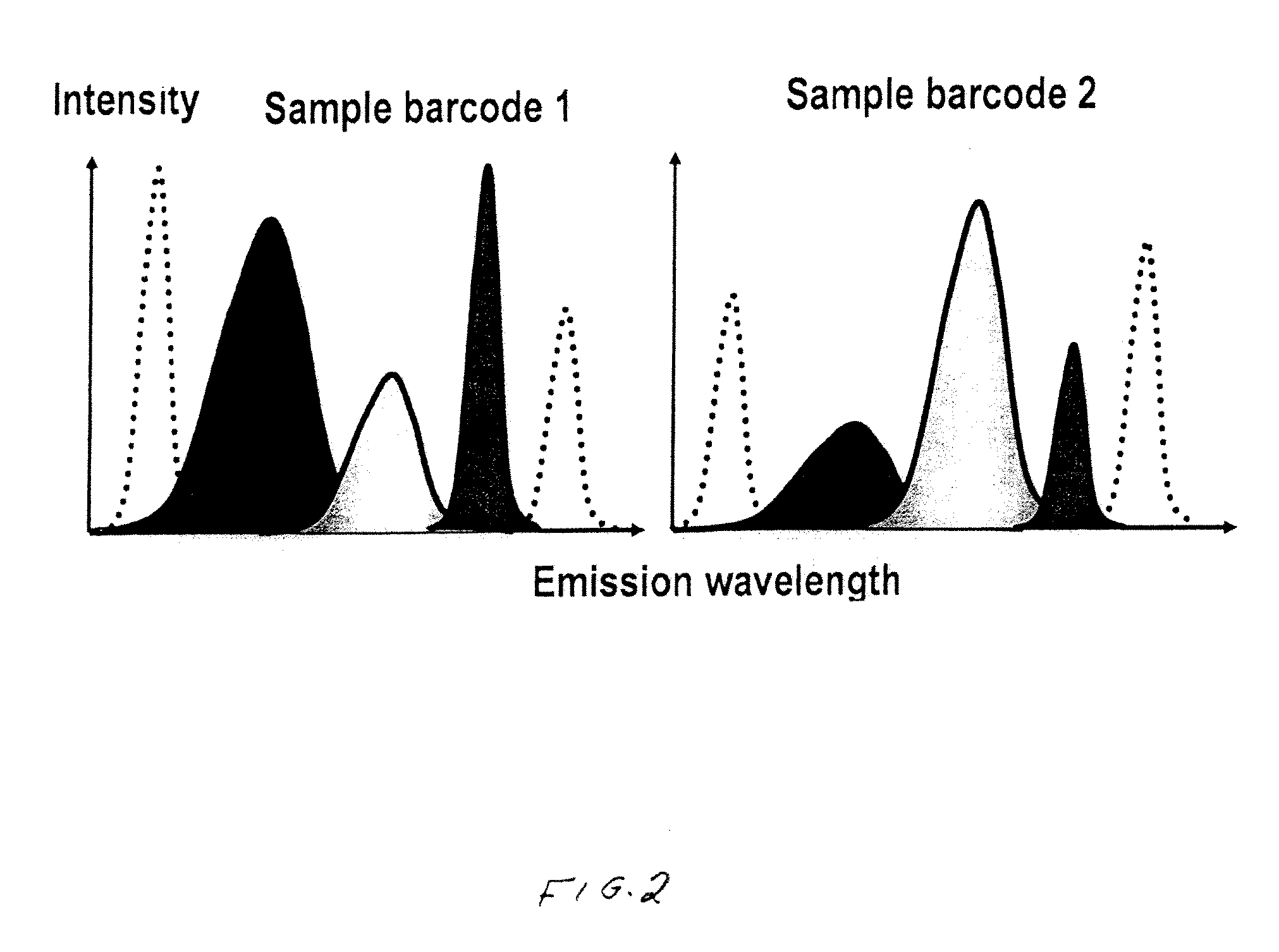
[0007] Luminescent materials according to various embodiments of the invention can exhibit a number of desirable characteristics. In some embodiments, the luminescent materials can exhibit photoluminescence with a high quantum efficiency, with a narrow spectral width, and with a peak emission wavelength located within a desirable range of wavelengths, such as the visible range or the near infrared range. Also, these photoluminescent characteristics can sometimes be relatively insensitive over a wide range of excitation wavelengths. The luminescent materials can have other desirable characteristics, such as relating to their band gap energies and electrical conductivities. Advantageously, the luminescent materials can be readily processed for use in anti-counterfeiting, inventory, photovoltaic, and other applications. For example, the luminescent materials can be used to form security markings that are difficult to reproduce and, thus, can be advantageously used in anti-counterfeiting applications. As another example, the luminescent materials can be used to form identification markings and, thus, can be advantageously used in inventory applications.

Problems solved by technology

While bar codes are useful for tracking locations or identities of objects, these markings can be readily reproduced and, thus, have limited effectiveness in terms of preventing counterfeiting.

Method used


Image

  • Luminescent materials that emit light in the visible range or the near infrared range
  • Luminescent materials that emit light in the visible range or the near infrared range
  • Luminescent materials that emit light in the visible range or the near infrared range

Examples


example 1

Formation of Luminescent Material

[0095] Anhydrous SnCl2 (or SnCl2.H2O) was mixed with CsI in a powdered form and then pressed with a standard pellet press (5 cm diameter, 5 mm thickness, 8 tons pressure). The ratio of SnCl2 (or SnCl2.H2O) to CsI was in the range of 0.1 percent to 99.5 percent by weight. The resulting material (in either a pellet form or a powdered form) was then tested for photoluminescence.

example 2

Formation of Luminescent Material

[0096] SnBr2 (or SnI2) was mixed with CsI in a powdered form. The ratio of SnBr2 (or SnI2) to CsI was in the range of 10 percent to 90 percent by weight. The resulting material in a powdered form was then tested for photoluminescence in the near infrared range.

example 3

Formation of Luminescent Material

[0097] Sn2P2O7 was mixed with CsI in a powdered form and then pressed with a standard pellet press (5 cm diameter, 5 mm thickness, 8 tons pressure). The ratio of Sn2P2O7 to CsI was in the range of 0.1 percent to 99.5 percent by weight. The resulting material (in either a pellet form or a powdered form) was then tested for photoluminescence.


PUM

PropertyMeasurementUnit
quantum efficiencyaaaaaaaaaa
Full Width at Half Maximumaaaaaaaaaa
quantum efficiencyaaaaaaaaaa

Abstract

Luminescent materials and the use of such materials in anti-counterfeiting, inventory, photovoltaic, and other applications are described herein. In one embodiment, a luminescent material has the formula: [AaBbXxX′x′X″x″][dopants], wherein A is selected from at least one of elements of Group IA; B is selected from at least one of elements of Group VA, elements of Group IB, elements of Group IIB, elements of Group IIIB, elements of Group IVB, and elements of Group VB; X, X′, and X″ are independently selected from at least one of elements of Group VIIB; the dopants include electron acceptors and electron donors; a is in the range of 1 to 9; b is in the range of 1 to 5; and x, x′, and x″ have a sum in the range of 1 to 9. The luminescent material exhibits photoluminescence having: (a) a quantum efficiency of at least 20 percent; (b) a spectral width no greater than 100 nm at Full Width at Half Maximum; and (c) a peak emission wavelength in the near infrared range.

Description

CROSS-REFERENCE TO RELATED APPLICATION [0001] This application claims the benefit of U.S. Provisional Application Ser. No. 60 / 784,863, filed on Mar. 21, 2006, the disclosure of which is incorporated herein by reference in its entirety.FIELD OF THE INVENTION [0002] The invention relates generally to luminescent materials. More particularly, the invention relates to luminescent materials that emit light in the visible range or the near infrared range and the use of such materials in anti-counterfeiting, inventory, photovoltaic, and other applications. BACKGROUND OF THE INVENTION [0003] An object to be authenticated or identified is sometimes provided with a specific marking, which can be part of the object itself or can be coupled to the object. For example, a commonly used marking is a bar code, which includes a linear array of elements that are either printed directly on an object or on labels that are coupled to the object. These elements typically include bars and spaces, with bar...

Claims


Application Information

Patent Timeline
Patent Type & Authority Applications(United States)
IPC IPC(8): B05D5/12B32B9/00
CPCC09K11/616C09K11/628C09K11/665C09K11/667C09K11/668C09K11/693C23C14/5806C09K11/7435C23C14/0694C09K11/613C23C14/30C23C14/24C23C14/16C09K11/72
Inventor VARADARAJAN, JOHNRESAN, MIRNAWU, FANXINPFENNINGER, WILLIAM M.VOCKIC, NEMANJAKENNEY, JOHN
Owner OMNIPV
Why Eureka
Try Eureka