Spectral width narrowing method, optical element and light source device

a spectral width and narrowing technology, applied in the field of spectral width narrowing methods, optical elements and light source devices, can solve the problems of inability to achieve high-speed wavelength conversion, inability to greatly change wavelengths, and require mechanical sweeping, etc., to achieve suppressed pedestal components (noise), high narrowing factor, and high narrowing factor

Active Publication Date: 2013-04-11
HAMAMATSU PHOTONICS KK
View PDF5 Cites 1 Cited by
  • Summary
  • Abstract
  • Description
  • Claims
  • Application Information

AI Technical Summary

Benefits of technology

[0014]The method for narrowing a spectral width of the present invention uses the optical waveguide member having the predetermined dispersion characteristics to cause the soliton effect in the input optical pulse, and thus can provide an output optical pulse in which the spectral width has been narrowed with a high narrowing factor, and the pedestal component (noise) is suppressed.
[0015]Using the method for narrowing a spectral width of the present invention, the optical element of the present invention can change the input optical pulse in a wide wavelength range to an output optical pulse in which the spectral width has been narrowed with a high narrowing factor, and the pedestal component (noise) is suppressed.
[0016]The light source device of the present invention can emit a soliton optical pulse with a narrow spectral width and a low noise component as an output optical pulse.

Problems solved by technology

In the case of a semiconductor laser, which is used as a conventional wavelength tunable light source, the variable wavelength band is limited to the gain band, and therefore the wavelength cannot be greatly changed.
However, this method requires mechanical sweeping and cannot achieve high-speed wavelength conversion.

Method used


Image

  • Spectral width narrowing method, optical element and light source device
  • Spectral width narrowing method, optical element and light source device
  • Spectral width narrowing method, optical element and light source device

Examples


Embodiment Construction

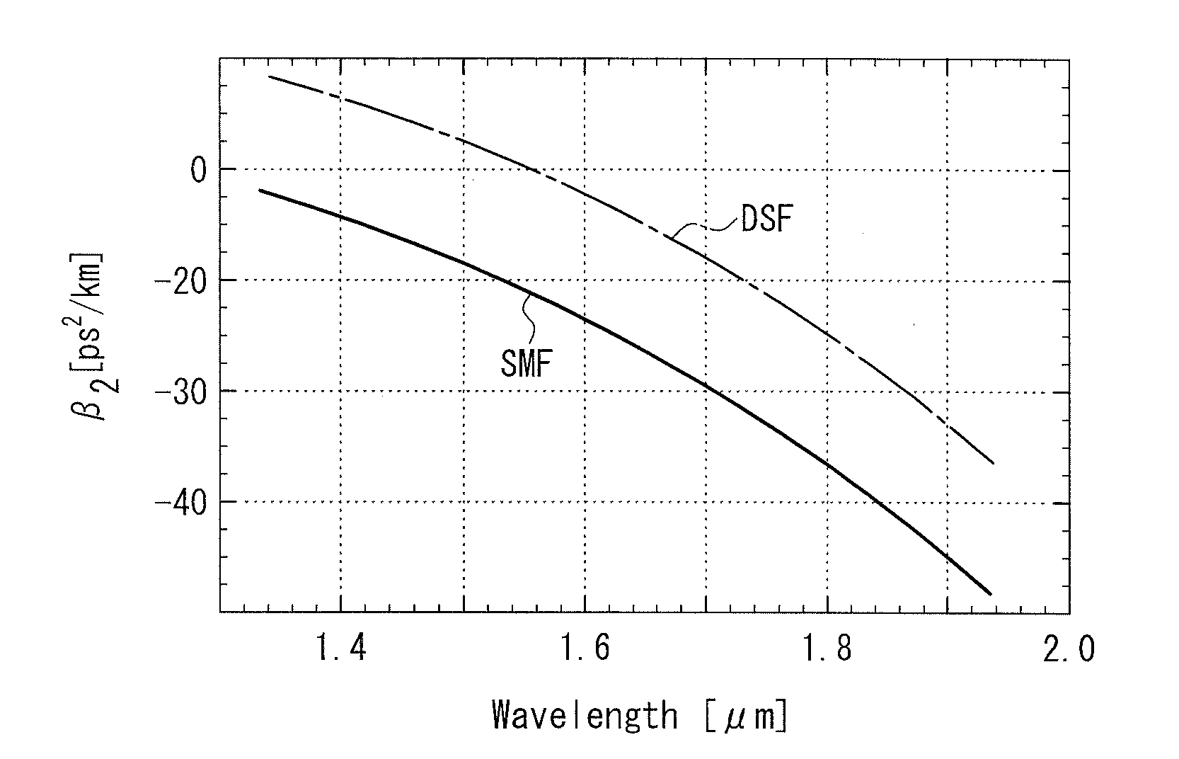
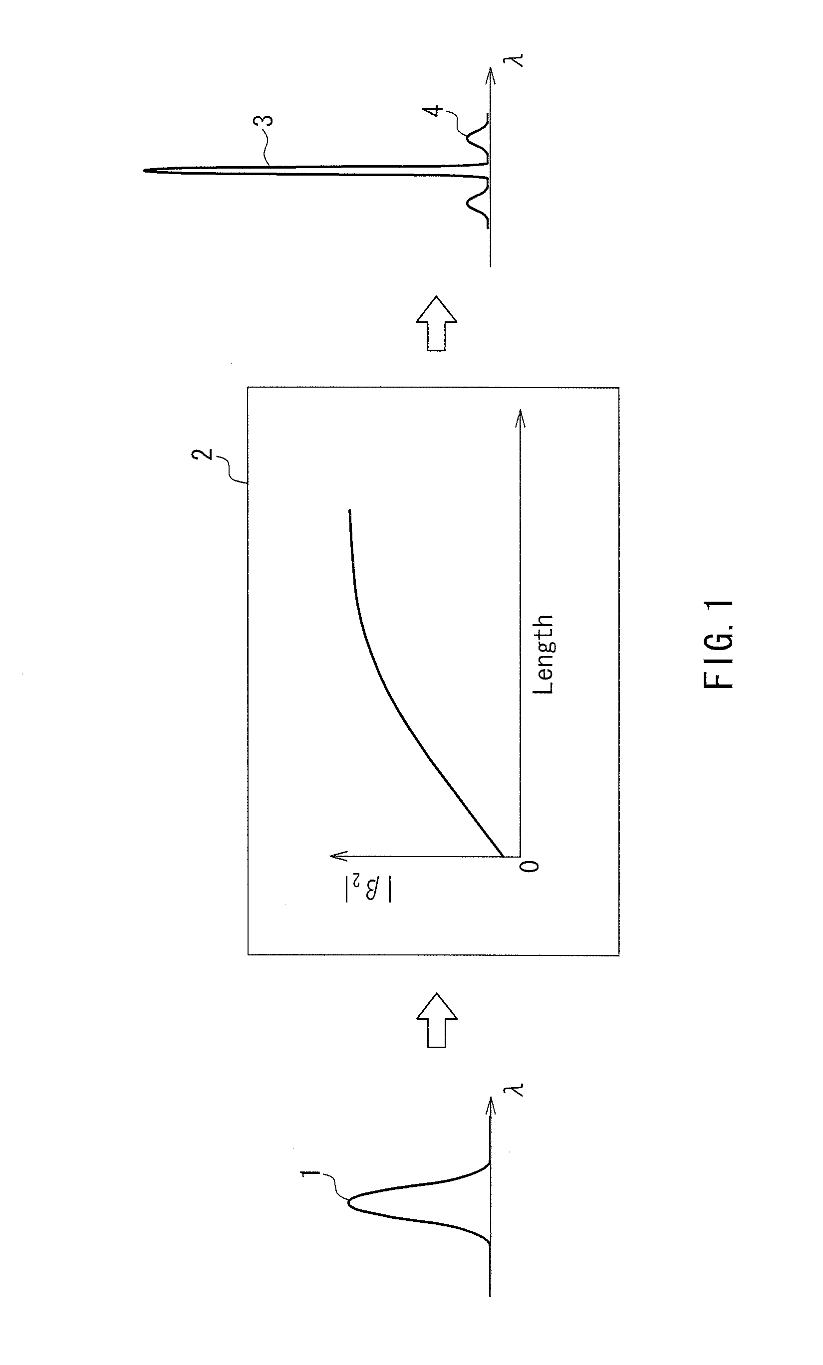
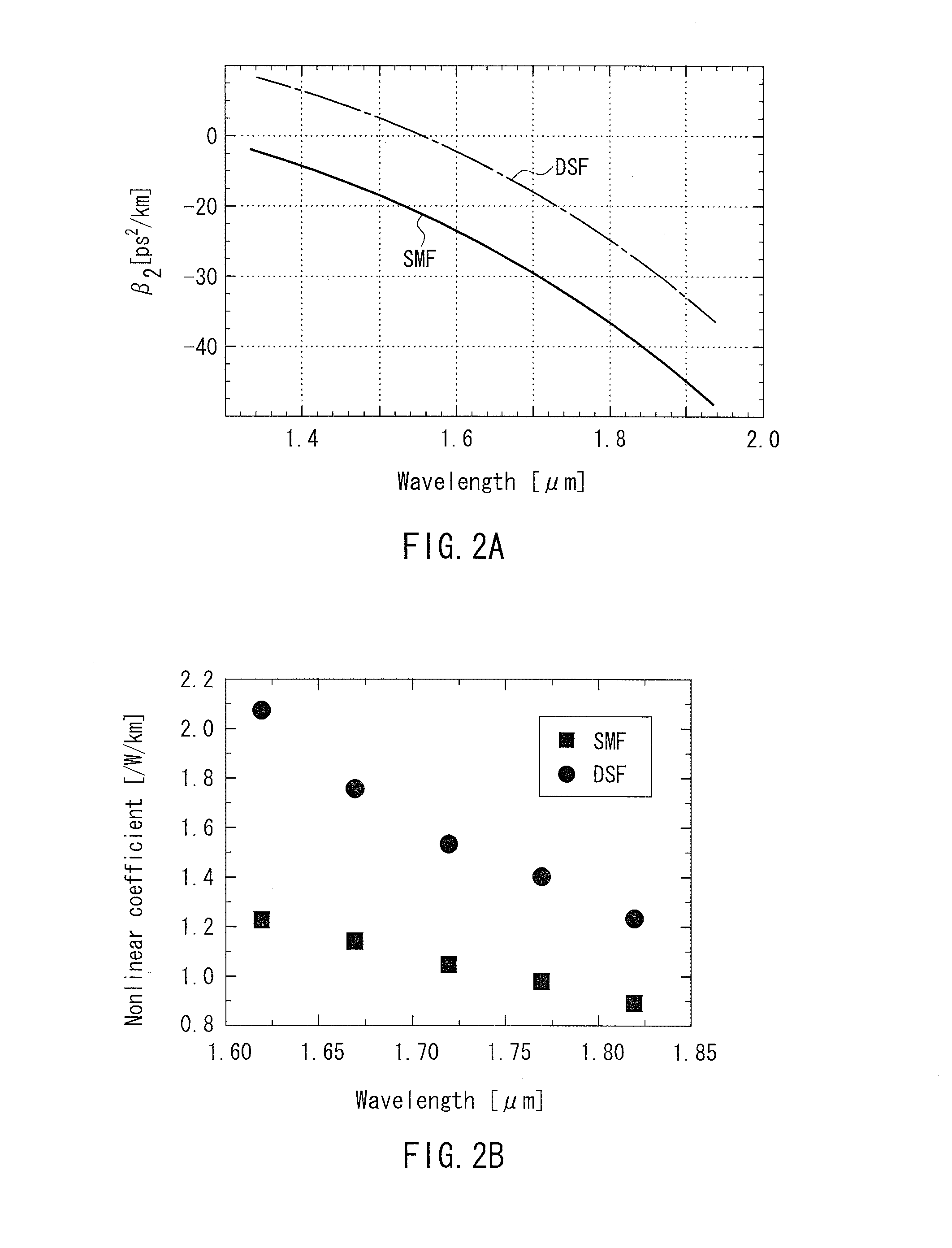
[0027]A method for narrowing a spectral width of the present invention includes using an optical waveguide member to cause a soliton effect in an input optical pulse within the optical waveguide member, thereby narrowing a spectral width of the input optical pulse to provide an output optical pulse, the optical waveguide member having dispersion characteristics such that an average of a second-order dispersion value (β2) with respect to the input optical pulse is negative, and an absolute value of the second-order dispersion value (β2) increases in a propagation direction of the input optical pulse.

[0028]With this configuration, as the optical pulse propagates in the optical waveguide member, the spectral width of the optical pulse becomes narrower due to the soliton effect of maintaining the soliton pulse characteristics. Therefore, optimizing the degree of the increase in the absolute value of the second-order dispersion value (β2) of the optical waveguide member in accordance wit...


PUM

PropertyMeasurementUnit
spectral widthaaaaaaaaaa
pulse widthaaaaaaaaaa
center wavelengthaaaaaaaaaa

Abstract

The present invention provides a method for narrowing a spectral width that can also be adapted to an ultrashort optical pulse emitted from a wavelength tunable light source, and that can provide an output optical pulse with a narrow spectral width and a low noise component, and an optical element and a light source device that use the method for narrowing a spectral width. The method includes using an optical waveguide member (2) to cause a soliton effect in an input optical pulse (1) within the optical waveguide member (2), thereby narrowing a spectral width of the input optical pulse (1) to provide an output optical pulse (3), the optical waveguide member (2) having dispersion characteristics such that the average of a second-order dispersion value (β2) with respect to the input optical pulse (1) is negative, and the absolute value of the second-order dispersion value (β2) increases in a propagation direction of the input optical pulse (1).

Description

TECHNICAL FIELD[0001]The present invention relates to a method for narrowing a spectral width that narrows the spectral width of an optical pulse, an optical element that uses this method to narrow the spectral width of input light and emits output light, and a light source that emits an optical pulse in which the spectral width has been narrowed.BACKGROUND ART[0002]In the fields of optical measurement and opto-electronics, a wavelength tunable light source capable of changing the wavelength over a wide band has become increasingly important.[0003]In the case of a semiconductor laser, which is used as a conventional wavelength tunable light source, the variable wavelength band is limited to the gain band, and therefore the wavelength cannot be greatly changed. For example, a method for changing the wavelength by rotating a diffraction grating also has been proposed. However, this method requires mechanical sweeping and cannot achieve high-speed wavelength conversion.[0004]To solve t...

Claims


Application Information

Patent Timeline
Patent Type & Authority Applications(United States)
IPC IPC(8): G02F1/39H01S3/067
CPCG02F1/395G02B6/02247G02F1/3513H01S3/067
Inventor NISHIZAWA, NORIHIKOOZEKI, YASUYUKIITOH, KAZUYOSHI
Owner HAMAMATSU PHOTONICS KK
Why Eureka
Try Eureka