Laser emission module for lidar

A technology of laser emission and laser radar, which is applied in the direction of lasers, phonon exciters, laser components, etc., can solve the problems of laser emission module system complexity, high cost, and difficulty in integration, and achieve uniform beam, narrow spectral width, and convenience integrated effect

Inactive Publication Date: 2019-09-20
深圳市柠檬光子科技有限公司
View PDF6 Cites 2 Cited by
  • Summary
  • Abstract
  • Description
  • Claims
  • Application Information

AI Technical Summary

Problems solved by technology

[0011] In order to solve the problem that the laser emission module system in related lidar technology is complex, not easy to integrate, and the cost is high, the present disclosure provides a laser emission module of lidar

Method used


Image

  • Laser emission module for lidar
  • Laser emission module for lidar
  • Laser emission module for lidar

Examples


Embodiment 1

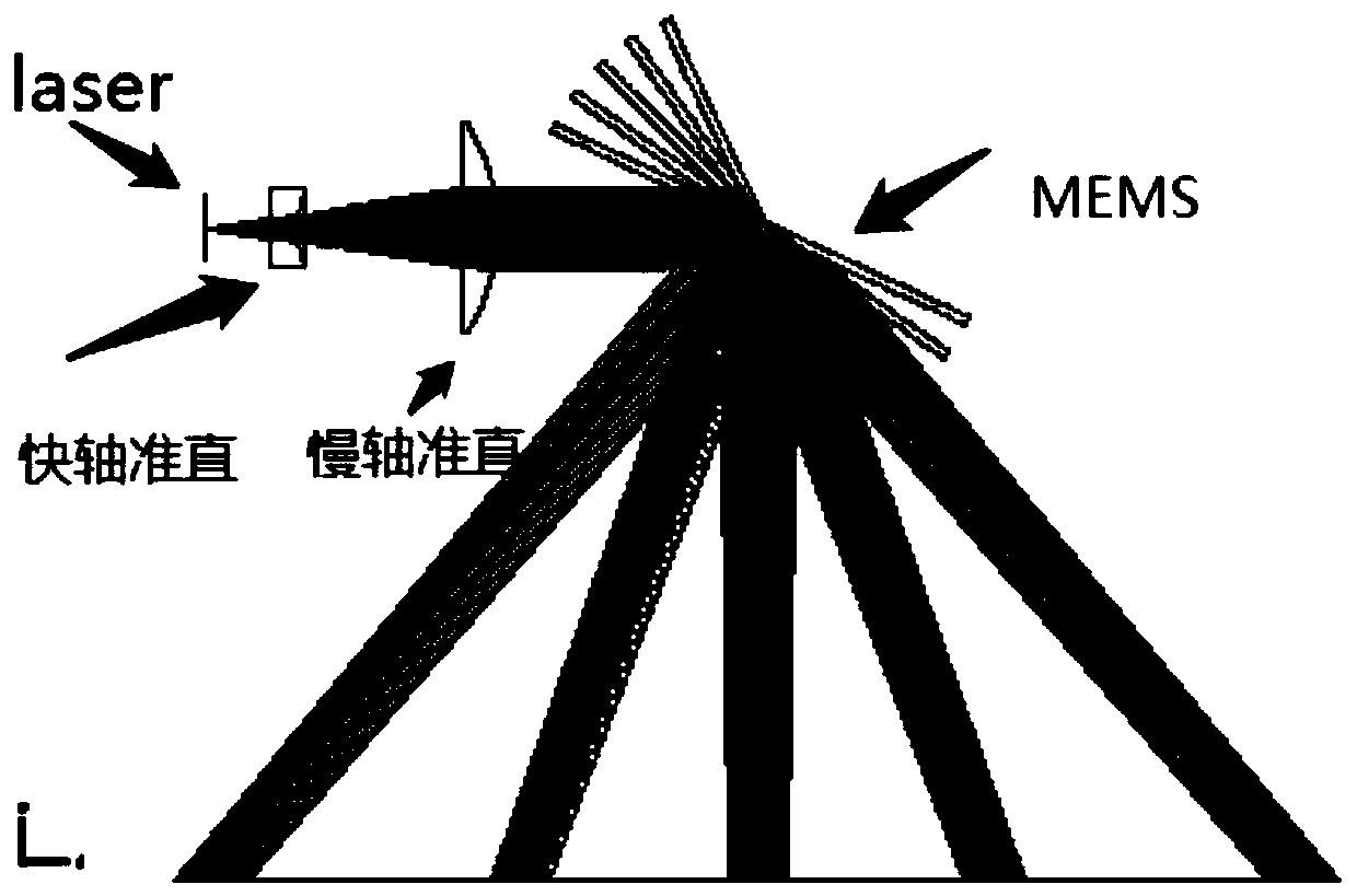
[0042] see Figure 4-5 , Figure 4-5 It is a schematic diagram of the optical path of a laser emitting module for a scanning laser radar according to an exemplary embodiment. Figure 4-5 Among them, the semiconductor laser chip in the laser emitting module is a HCSEL (Horizontal Cavity Surface Emitting Laser, horizontal cavity surface emitting laser) chip.

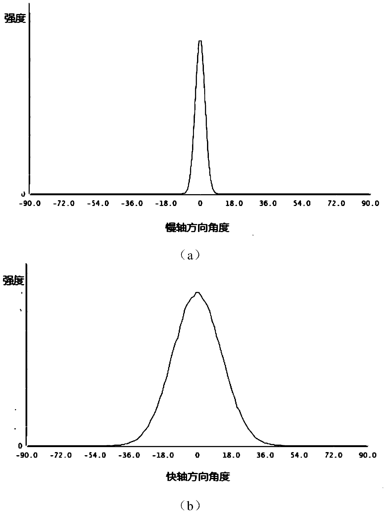
[0043] The light emitting surface of HCSEL does not require special cavity surface treatment, and the surface damage threshold is high; in addition, because the surface emits light, the light divergence angle is small, which avoids the problems attached to the large fast axis divergence angle, and the laser signal emitted by it has a direction Or the characteristics of collimation in two directions; the laser resonant cavity is longer and the light output area is large, which is an ideal high-power lighting source. At the same time, the HCSEL chip is simple to manufacture, and it is easier to integrate a two-dimensional ar...

Embodiment 2

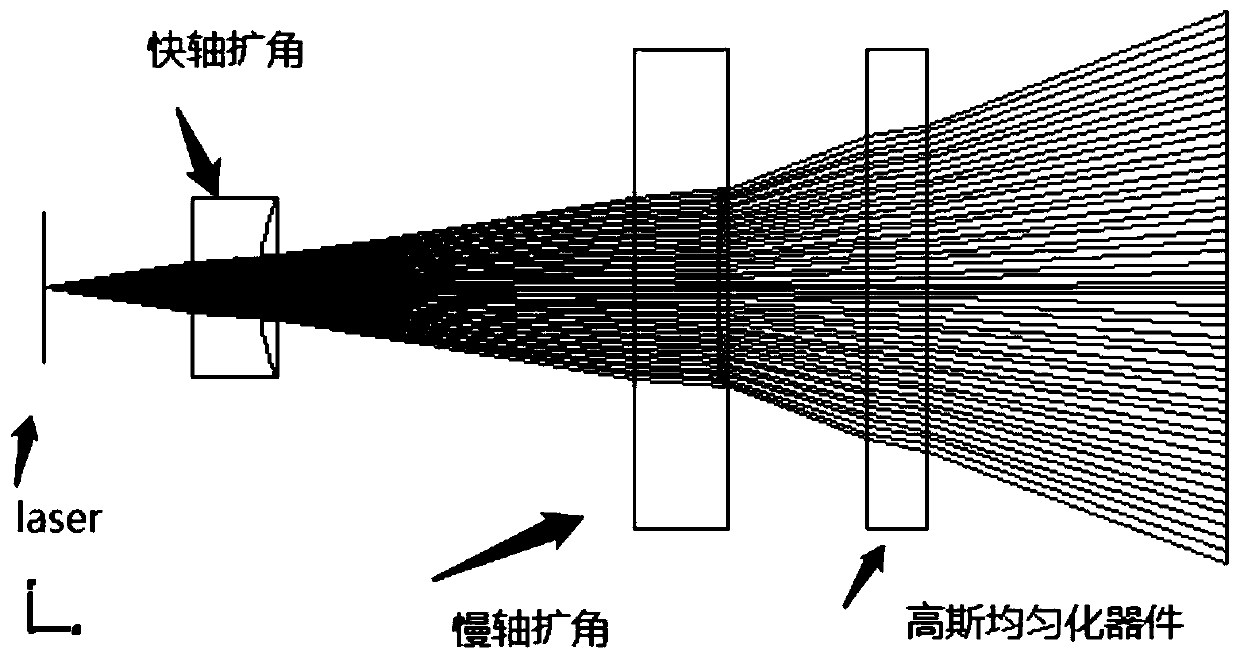
[0058] Such as Figure 10 As shown, in the 3D Flash lidar, the semiconductor laser chip in the laser emitting module is a horizontal cavity surface emitting laser (HCSEL) chip, and the laser emitting module also includes an angle expansion module, through which the laser emitted by the HCSEL chip The signal is processed by angle expansion, which expands the coverage of the laser signal in the corresponding direction, and can also make the light uniform in the coverage.

[0059] Specifically, the angle expansion module is a spherical mirror, an aspheric mirror, a binary optical element or a diffractive optical element.

[0060] Optionally, the angle expansion module includes a fast axis angle expansion module and a slow axis angle expansion module, both of which are located on the optical path of the light emitted by the horizontal cavity surface emitting laser (HCSEL) chip. The fast-axis and slow-axis rays are expanded by the fast-axis angle expansion module and the slow-axis...


PUM


Abstract

The invention discloses a laser emission module for lidar, which is characterized in that a semiconductor laser chip in the module is a horizontal cavity surface emitting laser (HCSEL) chip, and the laser light emitting by the HCSEL chip is collimated in at least one direction, so that the optical system is simplified; the laser emission module is enabled to have the characteristics of small central wavelength range, narrow spectral width, small wavelength temperature drift and the like without adding any optical devices through grating mode locking, and the HCSEL can simultaneously have a large light emitting area and a high-quality beam, thereby achieving the laser characteristics of high power, high brightness and uniform beam, and being very suitable for the application of long-distance and high-precision lidar. In addition, the power density of the light emitting surface is reduced due to the large light emitting area, and the life of the device is correspondingly prolonged. The laser chip structure and light emitting mode of the HCSEL can also reduce the chip cost and facilitate the integration with other optical devices in the module.

Description

technical field [0001] The invention relates to the technical field of laser devices, in particular to a laser emitting module for laser radar. Background technique [0002] Laser radar (LiDAR) mainly emits laser pulses by using semiconductor lasers in the near-infrared band, and then compares the received signal (target echo) reflected from the target with the transmitted signal, and obtains the target's signal after appropriate processing. Relevant information, such as target distance, azimuth, height, speed, attitude, and even shape parameters, so as to detect, track and identify objects such as cars, aircraft, missiles and other targets. It consists of a laser transmitter, an optical receiver, a turntable (for scanning radar) and an information processing system. The laser converts electrical pulses into optical pulses and sends them out, and the optical receiver restores the optical pulses reflected from the target into Electric pulses are sent to the display. [0003...

Claims


Application Information

Patent Timeline
Patent Type & Authority Applications(China)
IPC IPC(8): H01S5/18H01S5/12H01S5/022G01S7/481
CPCG01S7/4814H01S5/12H01S5/18H01S5/0225
Inventor 肖岩勾志勇周德来
Owner 深圳市柠檬光子科技有限公司
Why Eureka
Try Eureka