Device for Monitoring Respiratory Movements

a technology for respiratory movements and monitoring devices, applied in the field of respiratory movement monitoring devices, can solve the problems of insufficient respiration monitoring, patient exposure to a tremendous risk, and inability to measure the residual function capacity of the lungs, etc., and achieve the effect of reducing the mortality ra

Inactive Publication Date: 2008-01-17
BLOCK DAVID CESAR +1
View PDF3 Cites 68 Cited by
  • Summary
  • Abstract
  • Description
  • Claims
  • Application Information

AI Technical Summary

Benefits of technology

[0021] It is therefore one object of the present invention to provide a monitoring respiratory movements device to be used both in humans and animals for con

Problems solved by technology

The spirometers measure the lung capacity volume of a human being but they cannot measure the residual function capacity of the lungs.
However, both the spirometers and the pletismographs results obtained by the use of such devices generated a limited result based on the data obtained by those devices.
Nevertheless there is still some situations where the respiration monitoring is not fully developed leading to several holes in that field.
For example, while the removing from a patient the tubes from a life support machine, the patient is exposed to a tremendous risk where his body could not be prepared to breathe by it self.
Since the moment the tubes of the life support machine are removed from the patient, there is no more monitoring of the patient so the doctors can not tell whether the patient is able to breath by him self not until a few vital seconds and even minutes had passed by, wherein some times those seconds or minutes could lead so death.
It appears likely that SIDS may be caused by some subtle developmental delay, an anatomical defect or functional failure.
The problem for measuring the pressure values obtained by the respiration movements monitored from a human being or animal is to obtain reliable references to perform the tests.
When using a transducer under the mattress, as mentioned before, the changes of pressure produced by the respiration movements are partially absorbed by the mattress itself therefore the reading obtained by the transducer as not quite accurate.
In the e

Method used


Image

  • Device for Monitoring Respiratory Movements
  • Device for Monitoring Respiratory Movements
  • Device for Monitoring Respiratory Movements

Examples


Embodiment Construction

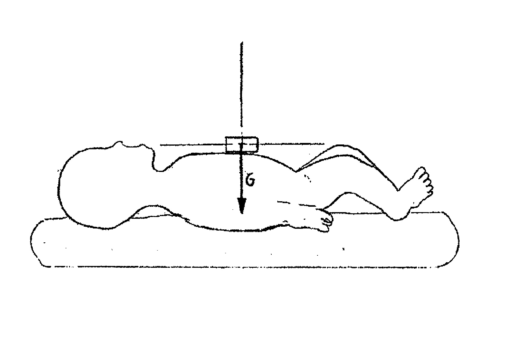
[0038] As stated before, even though the present invention can be used either for human or animal respiration monitoring, the following description is based exclusively in the monitoring of respiration movements of infants, and specially in one month to one year old babies. Therefore, the following example should not be considered as a limit to the scope and spirit of the present invention.

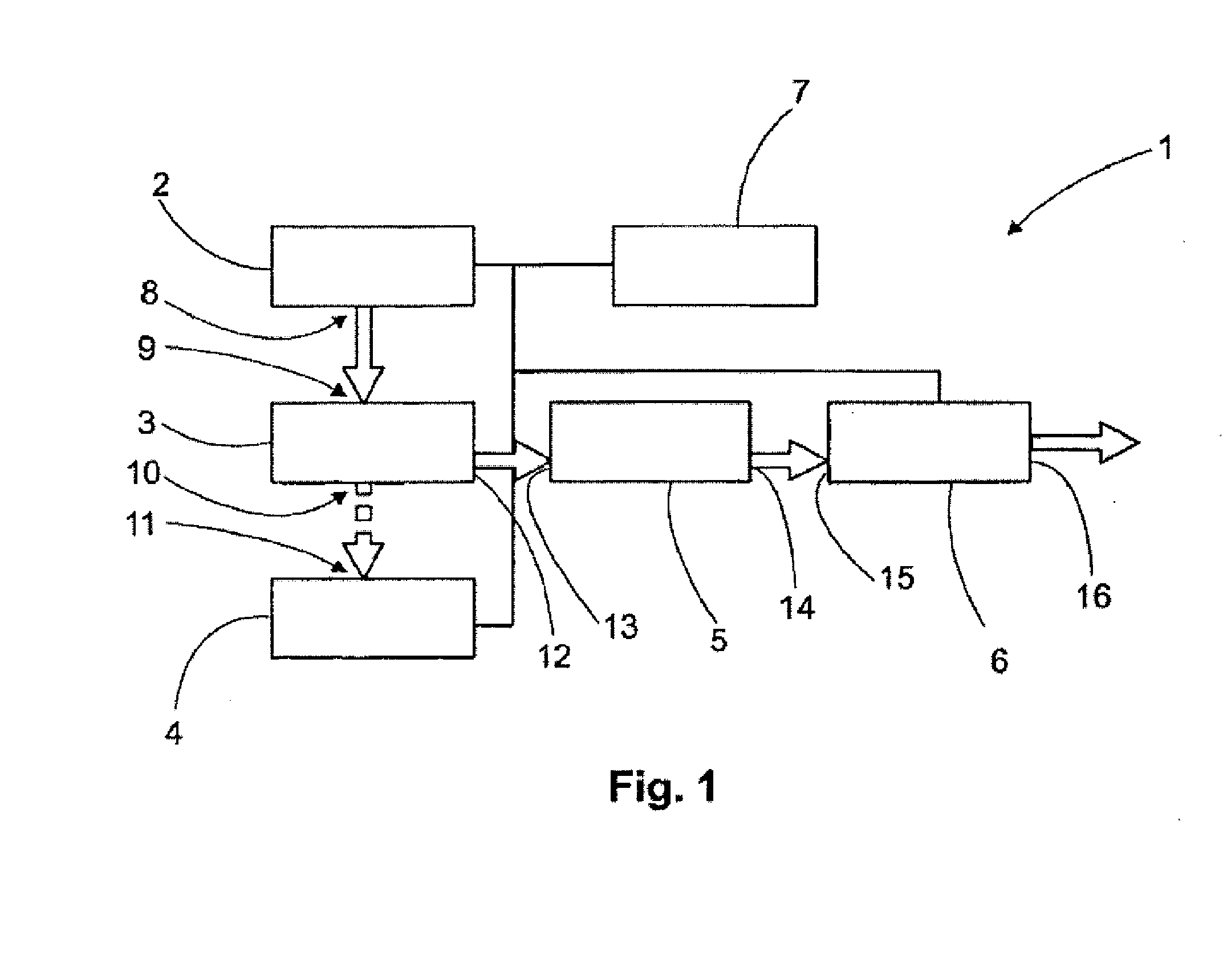
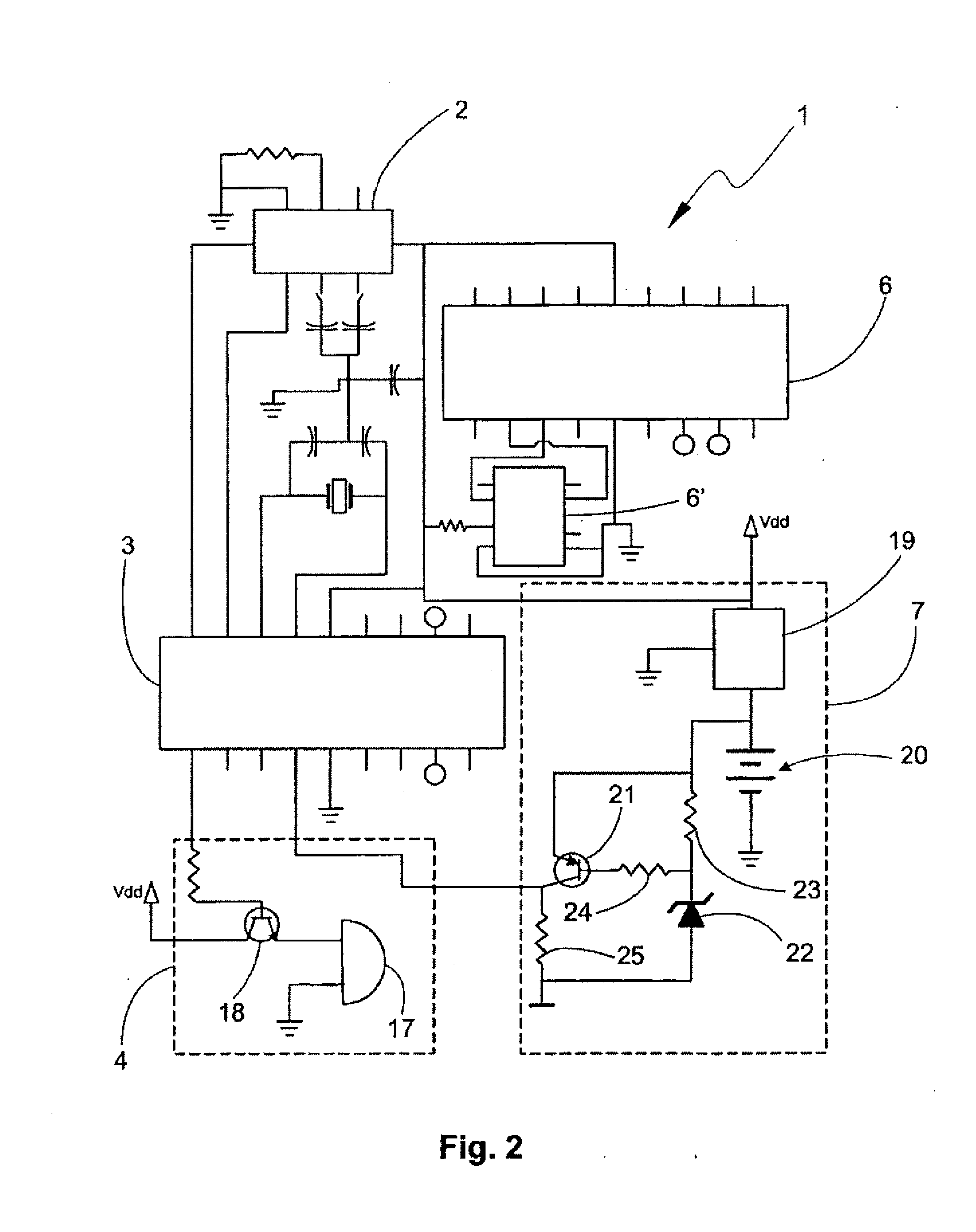
[0039] Now referring in detail to FIG. 1, the monitoring respiration movement device is defined by an electronic circuit generally described with the reference number 1. Said electronic circuit 1 comprises an accelerometer 2 including a motion detector, such as the one showed in FIG. 4. A micro controller 3, alarm means 4, instant acceleration transmission means defined by a series / parallel converting module 5 and a signal transmission module 6, and a feeding source 7 are also connected to the electronic circuit 1.

[0040] The accelerometer 2, being in this embodiment an ADXL202, is an acceleromet...


PUM


Abstract

The present invention relates to a monitor respiration movements device to be used on humans and also on animals for controlling the respiration movements and to control the apnea periods on infants, wherein the device reduces the mortality rate caused by the sudden instant death syndrome (SIDS), wherein the device comprises an accelerometer and a micro controller, with the accelerometer including a motion detector and a plurality of output plugs, the micro controller includes a plurality of input sockets, and wherein the plurality of output plugs are connected to the plurality of input sockets and the micro controller includes signal outputs which are connected to an alarm.

Description

CROSS REFERENCE TO RELATED APPLICATIONS [0001] The present application is a continuation-in-part application of U.S. patent application Ser. No. 10 / 534,166, filed May 5, 2005, the disclosure of which is incorporated herein by reference and from which priority benefit is claimed.BACKGROUND OF THE INVENTION [0002] 1. Field of the Invention [0003] The present invention relates to a device for monitoring respiratory movements for controlling apnea periods both in humans and in animals. Furthermore the present invention is related to a device for reducing the mortality rate caused by the sudden instant death syndrome (SIDS). [0004] 2. Description of the Prior Art [0005] The study of respiratory movements and lung capacity is considered a major subject in the medicine filed. For such studies several methods and technologies have been used gathering every bit of information that could lead to a better detection and diagnosis of lung and respiratory dysfunction. [0006] The use of spirometer...

Claims


Application Information

Patent Timeline
IPC IPC(8): A61B5/08
CPCA61B5/4818A61B5/113
Inventor SILVA, CARLOS DANIEL
Owner BLOCK DAVID CESAR
Why Eureka
Try Eureka