Aircraft engine inlet having zone of deformation

a technology of inlet assembly and aircraft engine, which is applied in the direction of liquid fuel engine components, non-positive displacement fluid engines, combustion air/fuel air treatment, etc., can solve the problems of increasing the weight and cost of the nacelle, high load on the fan housing, etc., and achieve the effect of preventing fractur

Active Publication Date: 2008-01-24
ROHR INC
View PDF23 Cites 35 Cited by
  • Summary
  • Abstract
  • Description
  • Claims
  • Application Information

AI Technical Summary

Benefits of technology

[0005]In general, one aspect of the present invention is generally directed to an inlet assembly for a turbofan engine nacelle comprising an inner barrel, an outer barrel radially spaced from the inner barrel, and a rear support for supporting the outer barrel relative to the inner barrel. The rear support comprises at least one plate extending between the inner barrel and the outer barrel for forming a closed axial end of the inlet assembly. The plate has at least one stiffener extending radially across the plate and at least one energy absorber formed in the plate. The energy absorber defines a zone of deformation adjacent the inner barrel. The rear support is deformable in the zone of deformation in response to an applied force during a fan blade-out event to prevent fracture of the rear support.

Problems solved by technology

However, the fan is generally unbalanced and thus continued rotation of the fan can cause high loads on the fan housing.
The use of structural support members on the aft bulkheads of prior art inlet assemblies, however, increases the weight and cost of the nacelle.

Method used


Image

  • Aircraft engine inlet having zone of deformation
  • Aircraft engine inlet having zone of deformation
  • Aircraft engine inlet having zone of deformation

Examples


Embodiment Construction

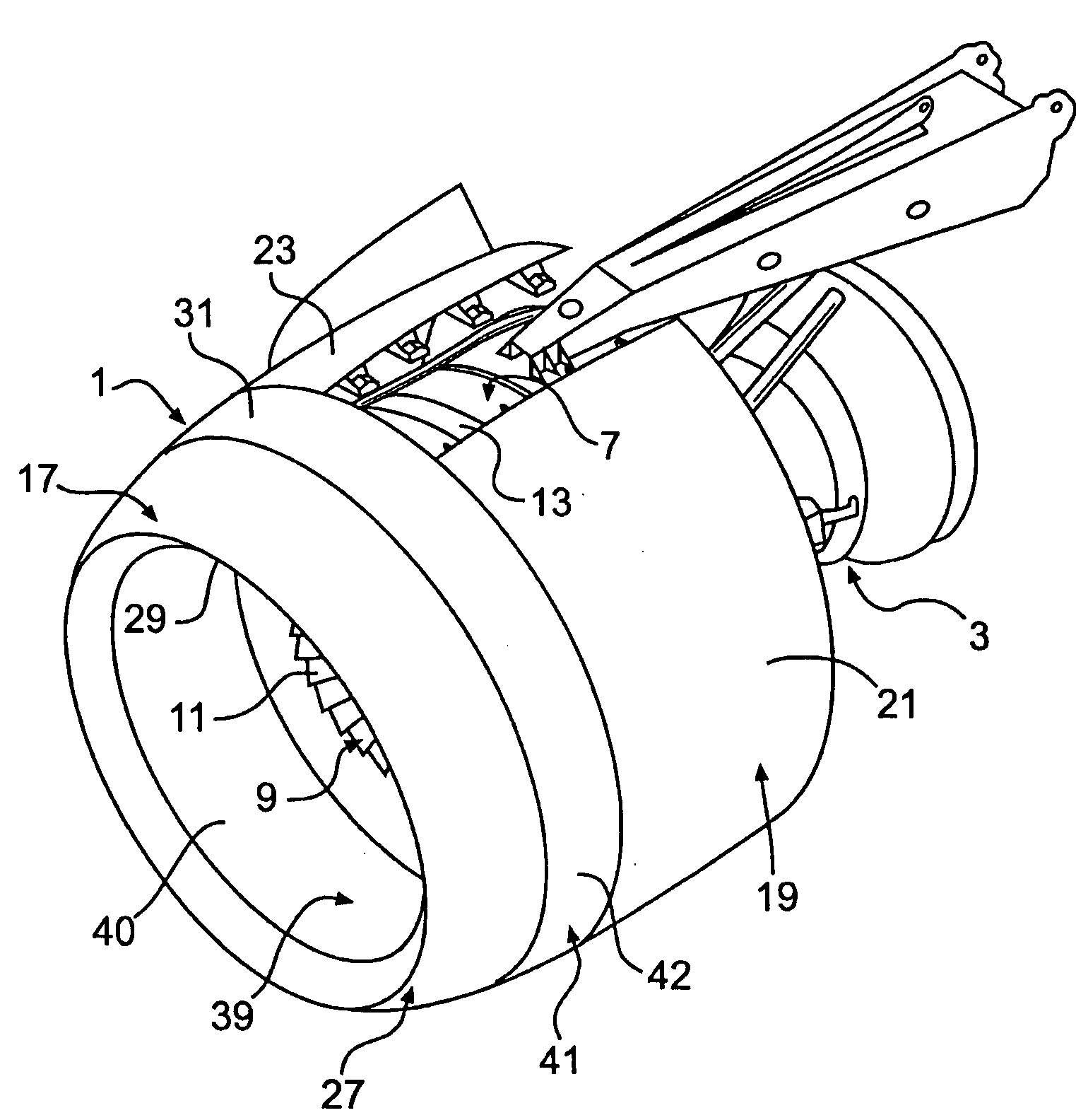
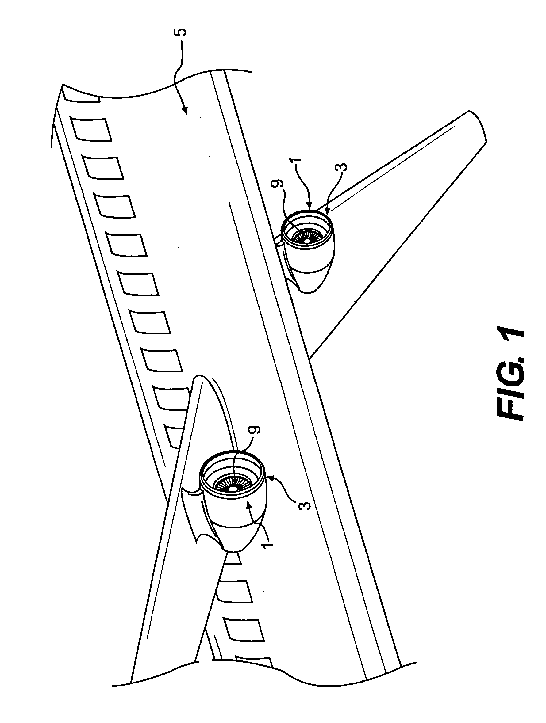
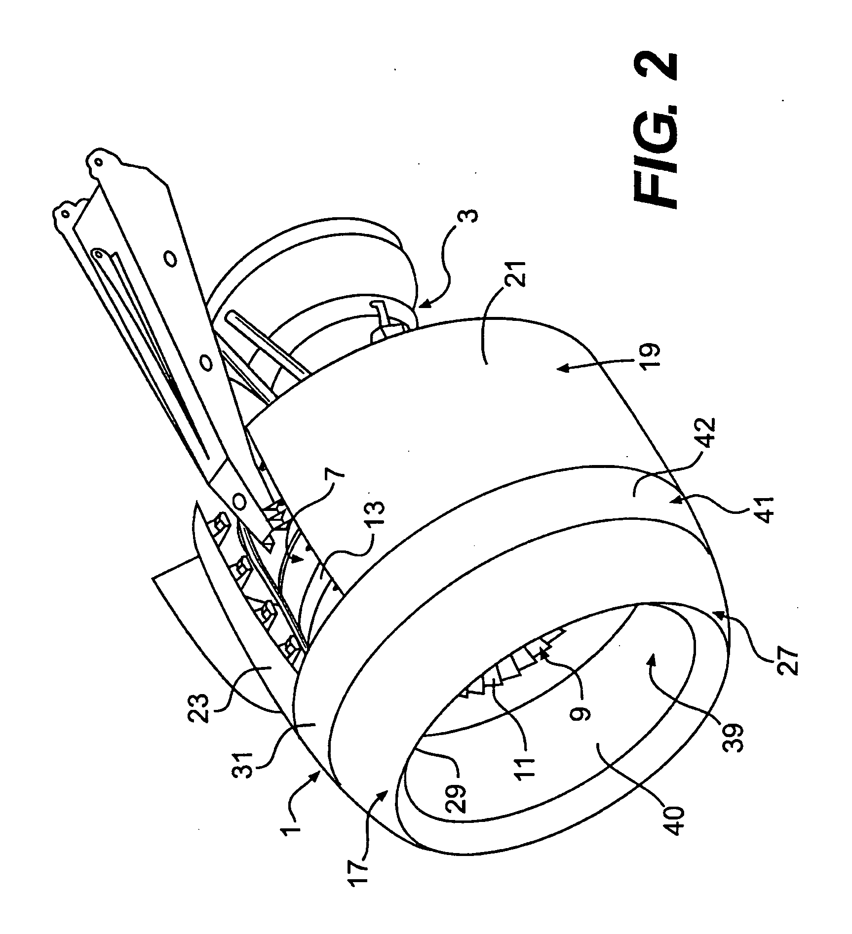
[0015]Referring now to the drawings in which like numerals indicate like parts throughout the several views, the present invention generally relates to a nacelle, generally indicated at 1 in FIG. 1, for a turbofan jet engine 3, mounted on an aircraft 5. As shown in FIG. 1, the nacelle 1 encloses the engine 3 and forms the outer aerodynamic covering of the engine. As shown in FIG. 2, the turbofan jet engine 3 includes a fan assembly, generally indicated at 7, located towards the front of the engine and having a fan 9 having fan blades 11 rotatably mounted in a fan housing 13 of the engine. It is understood that the nacelle 1 is only partially shown in FIG. 2 and includes an inlet assembly 17, mounted on the front of the fan assembly 7 and a fan cowl 19, including doors 21, 23 that enclose the fan assembly. It further is understood that the nacelle 1 may include other components and systems not shown in the illustrated embodiments (e.g., thrust reverser and de-icing system) without de...


PUM

PropertyMeasurementUnit
diameteraaaaaaaaaa
inner radius R2aaaaaaaaaa

Abstract

An inlet assembly for an aircraft engine nacelle includes an inner barrel, an outer barrel radially spaced from the inner barrel, and a rear support for supporting the outer barrel relative to the inner barrel. The rear support includes at least one radially extending stiffener and at least one energy absorber defining a zone of deformation adjacent the inner barrel. The rear support is deformable in the zone of deformation in response to forces applied during a fan blade-out event to prevent fracture of the rear support.

Description

FIELD OF THE INVENTION[0001]The present invention generally relates to gas turbine engines, and more specifically to an inlet assembly for an aircraft engine nacelle having a rear support with an energy absorbing zone.BACKGROUND OF THE INVENTION[0002]One type of jet engine typically used on large commercial airliners is a turbofan jet engine. Such turbofan engines have a compressor, combustor and turbine, and include a fan mounted on the front of the engine. These fans, some as large as 10 feet in diameter, draw air into the engine. Some of the air is sent to the compressor and the combustor, while the rest bypasses these components through ducts along the outside of the engine. The fans include fan blades that rotate at speeds up to approximately 9,000 rpm during operation of the engine and are enclosed in a fan housing that radially surrounds the fan. Turbofan engines for airliners typically include a nacelle that at least partially surrounds the engine and provides an aerodynamic...

Claims


Application Information

Patent Timeline
Patent Type & Authority Applications(United States)
IPC IPC(8): F02K3/02
CPCB64D29/02B64D2027/264F01D21/045Y10T29/49826F02K3/02Y02T50/672F05D2240/14F02C7/04Y02T50/60Y10T137/0536
Inventor SHUTRUMP, JEFFREY D.
Owner ROHR INC
Why Eureka
Try Eureka