Solar Collector

a technology of solar collectors and collectors, applied in the field of solar collectors, can solve the problems of low efficiency of solar collectors, low efficiency of finished collectors, and low efficiency of collectors, and achieve the effect of improving efficiency and extra cos

Inactive Publication Date: 2008-01-24
BROCKHOFF BRUCE WINSTON
View PDF6 Cites 17 Cited by
  • Summary
  • Abstract
  • Description
  • Claims
  • Application Information

AI Technical Summary

Benefits of technology

[0010] In some examples, the heat collected by the solar collector can be used to preheat fluids that are then passed through known traditional solar collectors that heat those fluids. In this way, significantly improved efficiency can be achieved for substantially little extra cost over and above the cost of the traditional solar collectors. This cost is substantially less than a corresponding duplication of the known solar collectors.

Problems solved by technology

Many designs have been proposed but, in general, the finished collectors are expensive.
Whilst these types of water collectors can be relatively efficient compared to the swimming pool solar collectors referred to above, the comparative per unit cost of the collectors is considerable.
Accordingly, this is one contributing factor to the lack of wide spread adoption of the technology.

Method used


Image

  • Solar Collector
  • Solar Collector
  • Solar Collector

Examples


Embodiment Construction

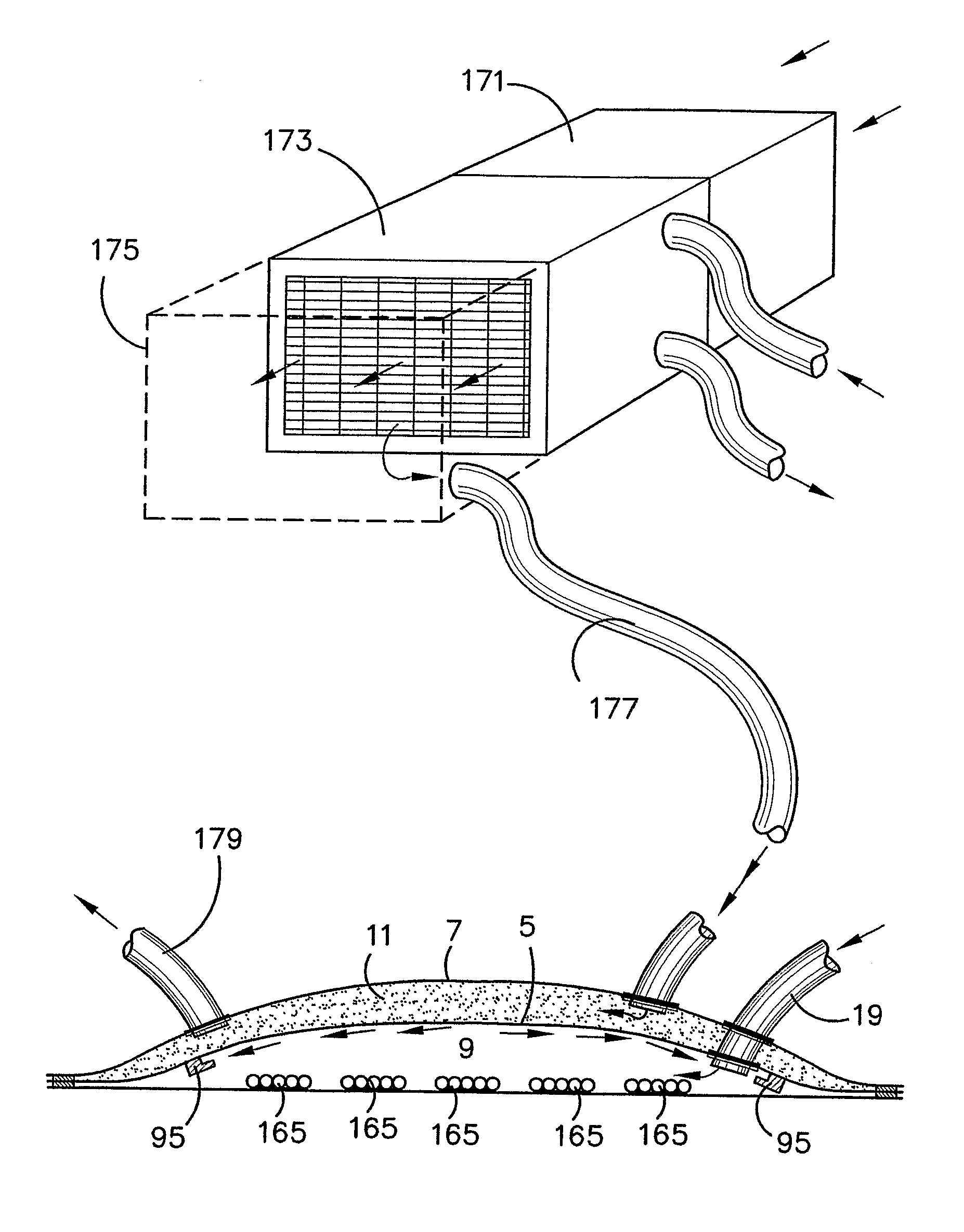
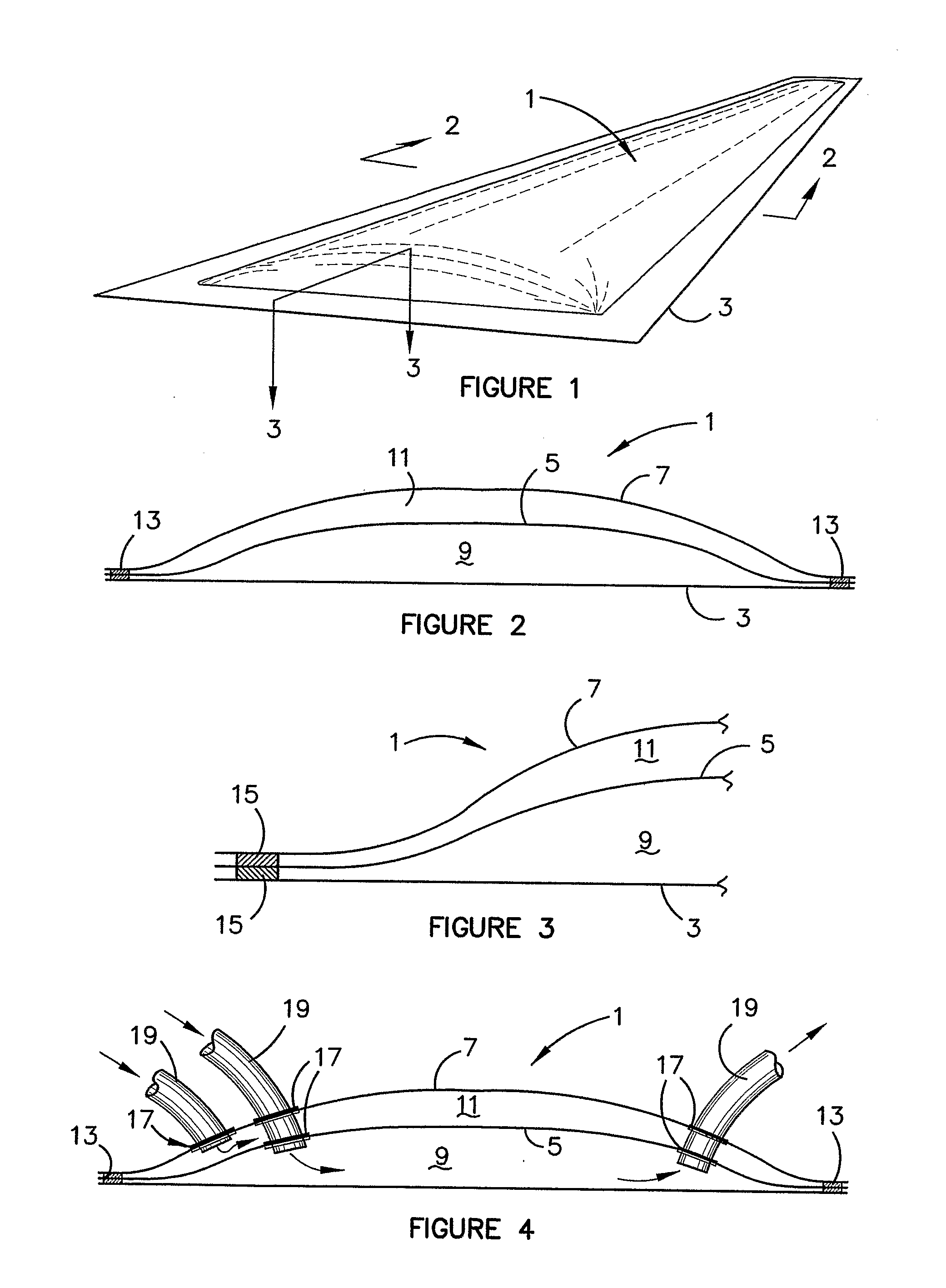
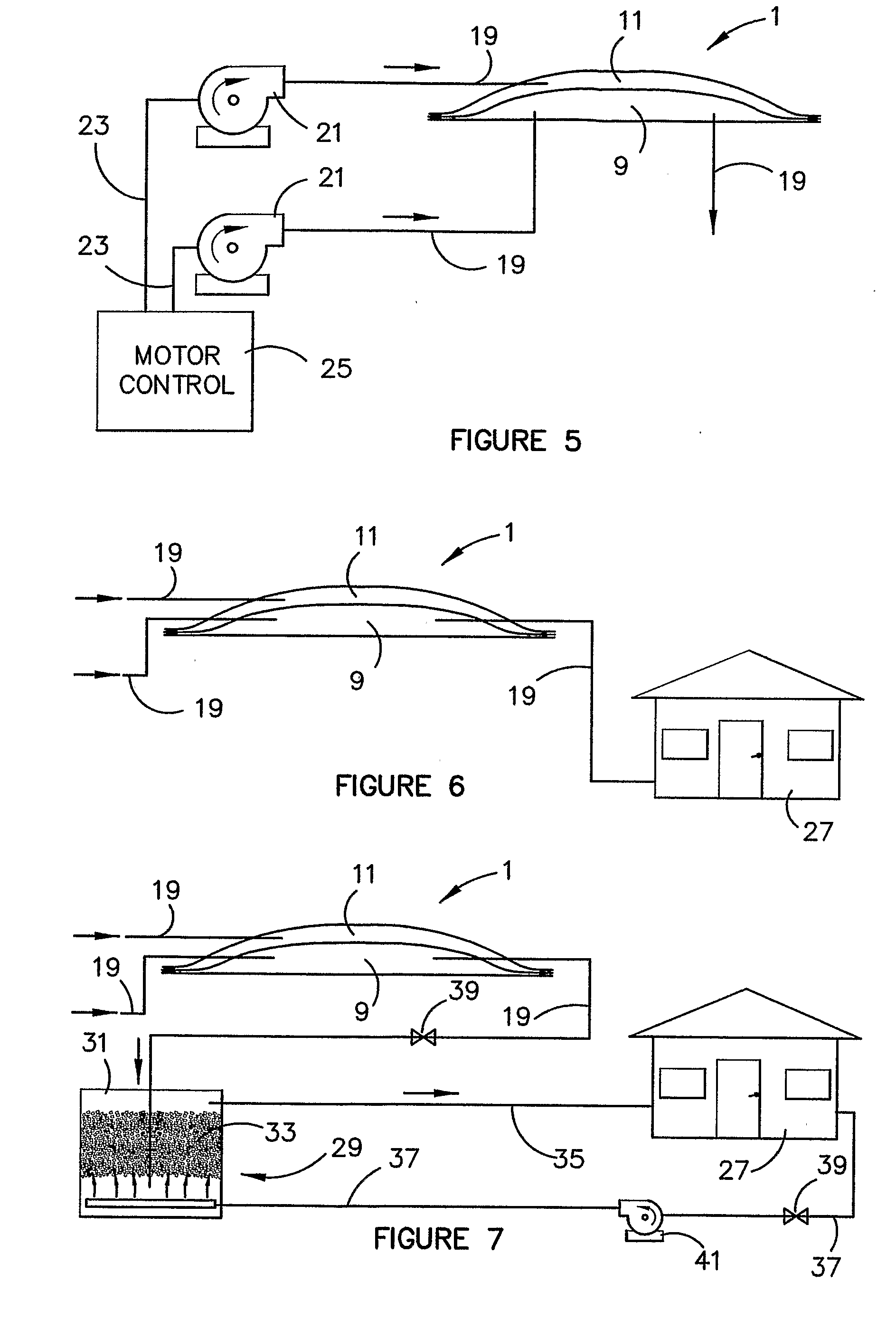
[0081] Referring firstly to the solar collector shown in FIGS. 1 through 4 it can be seen that the solar collector is in the form of a flume 1 that has a base part 3 of a plastics material UV stabilised P.V.C. sheet. The P.V.C. sheet is typically about 180 microns in thickness. The exact thickness is not critical.

[0082] Typically, the base part is an elongate strip, and in one embodiment it is typically one meter wide. The length of the flume may be of any desired length but typically it is many meters in length and can extend over many hundreds of meters if required. A plastics materials sheet first covering 5 overlays the base part 3. A further plastics material sheet second covering 7 overlays the first covering 5. The first covering 5 and the second covering 7 are sealingly interconnected relative to the base part 5 to define deflated first air chamber 9 and second air chamber 11. The sealing is preferably by welding along the side edges of the flume and has been shown generall...


PUM

PropertyMeasurementUnit
thicknessaaaaaaaaaa
diameteraaaaaaaaaa
flow rateaaaaaaaaaa

Abstract

A solar collector (1) is provided from plastics material sheets. There is a base part (3) and a first covering (5) overlying the base part (3). A first chamber (9) exists between the base part (3) and the first covering (5). The sheets are scaled at their side edges. The surface of the base part (5) that faces internally of the first chamber is heat absorbing to assist solar energy absorption into the first chamber (9). The first chamber (9) is supplied with a positive pressure air from a fan or blower and inflates the collector. The air is, in turn, heated by solar energy absorbed and can be used to heat water or other liquids directly within the collector (1) or the heated air can be taken from the collector (1) and used for heating. In a variation a second covering (7) overlies the first covering (5) and provides a second chamber (11) which is also inflated with positive pressure air. A method of obtaining drinkable/potable water using the solar collector is also disclosed. In addition a method of recovering minerals from liquids using the solar collector is also disclosed. Air in the second chamber acts as a heat insulating medium relative to atmospheric air and allows solar energy to be collected in the air in the first chamber by solar energy from atmosphere passing through the air in second chamber.

Description

FIELD OF THE INVENTION [0001] This invention relates to a solar collector and relates particularly but not exclusively to a collector that is used to heat air or water or other like media. [0002] This application is based on and claims the benefit of the filing date of U.S. application Ser. No. 60 / 585,523 filed 6 Jul. 2004 the contents of which are incorporated herein by reference in its entirety.BACKGROUND ART [0003] Hitherto extensive research has been undertaken into solar collectors for heating fluids such as water and / or air. For solar collectors for swimming pools the heat collectors, in general, comprise black plastics material either in pipe form or in black interconnected spaghetti type extruded form. The collector material is placed on a surface such as a roof of a building and the swimming pool water is circulated through the collectors and heated by the sun. Many designs have been proposed but, in general, the finished collectors are expensive. [0004] In domestic hot wat...

Claims


Application Information

Patent Timeline
Patent Type & Authority Applications(United States)
IPC IPC(8): C02F1/14F24J2/36F24S10/40F24S10/60F24S10/70
CPCB01D3/346B01D5/0066C02F1/10C02F1/14F24J2/0461Y02E10/44F24J2/208F24J2/23F24J2/32F24J2002/502Y02B10/20F24J2/0477F24S10/10F24S10/20F24S10/506F24S10/60F24S10/95F24S2080/502F24S2080/503Y02W10/37Y02A20/00Y02A20/211Y02A20/212
Inventor BROCKHOFF, BRUCE WINSTON
Owner BROCKHOFF BRUCE WINSTON
Why Eureka
Try Eureka