Gripping gasket

a gasket and sealing technology, applied in the field of gaskets, can solve the problems of adversely affecting the sealing and locking of the gasket, and achieve the effects of enhancing the rolling contact, increasing the frictional contact, and suitable roughness

Inactive Publication Date: 2008-01-24
STAR PIPE PRODS
View PDF14 Cites 9 Cited by
  • Summary
  • Abstract
  • Description
  • Claims
  • Application Information

AI Technical Summary

Benefits of technology

[0008] In certain embodiments, the blunt tooth can include features and elements for enhancing the rolling contact between the blunt tooth and the front wall of the socket end. For instance, the blunt tooth can have a contacting face of a specialized geometry (e.g. convex, concave, flat, etc.) to selectively adjust the location of initial contact, contact pressure, or other parameter (e.g., contact dynamics). Additionally, a roughened surface on the blunt tooth can be used to increase the frictional contact between the blunt tooth and the front wall. Suitable roughness can be obtained by using an irregular surface formed by grit blasting, chemical etches, spline protrusions, knurled protrusions, impregnated grit, composite constructions, bonded elements, and coated elements.
[0009] In embodiments, the embedded element can also include arrangements to enhance the locking function provided by the gripping elements, facilitate assembly, improve product life and improve performance, etc. For instance, the embedded element can include least four teeth arranged such that no more than two teeth grip the outer surface of the spigot end when the spigot end is inserted into the socket end. For instance, at least three can lie along a common arc. Additionally, the embedded element can include a ridge extending radially outwardly from the embedded element to limit the movement of the blunt tooth along the front face. In certain embodiments, at least one tooth includes a transverse groove that enhances the tooth's ability to penetrate into the outer surface of the spigot.

Problems solved by technology

The ability of the gasket to seal and lock the joint, however, can be adversely affected by such dimensional variations.
Moreover, there is a persistent need for gaskets that lock or retain a joint without unduly compromising the structure of the pipe (e.g., excessive penetration).

Method used


Image

  • Gripping gasket
  • Gripping gasket
  • Gripping gasket

Examples


Embodiment Construction

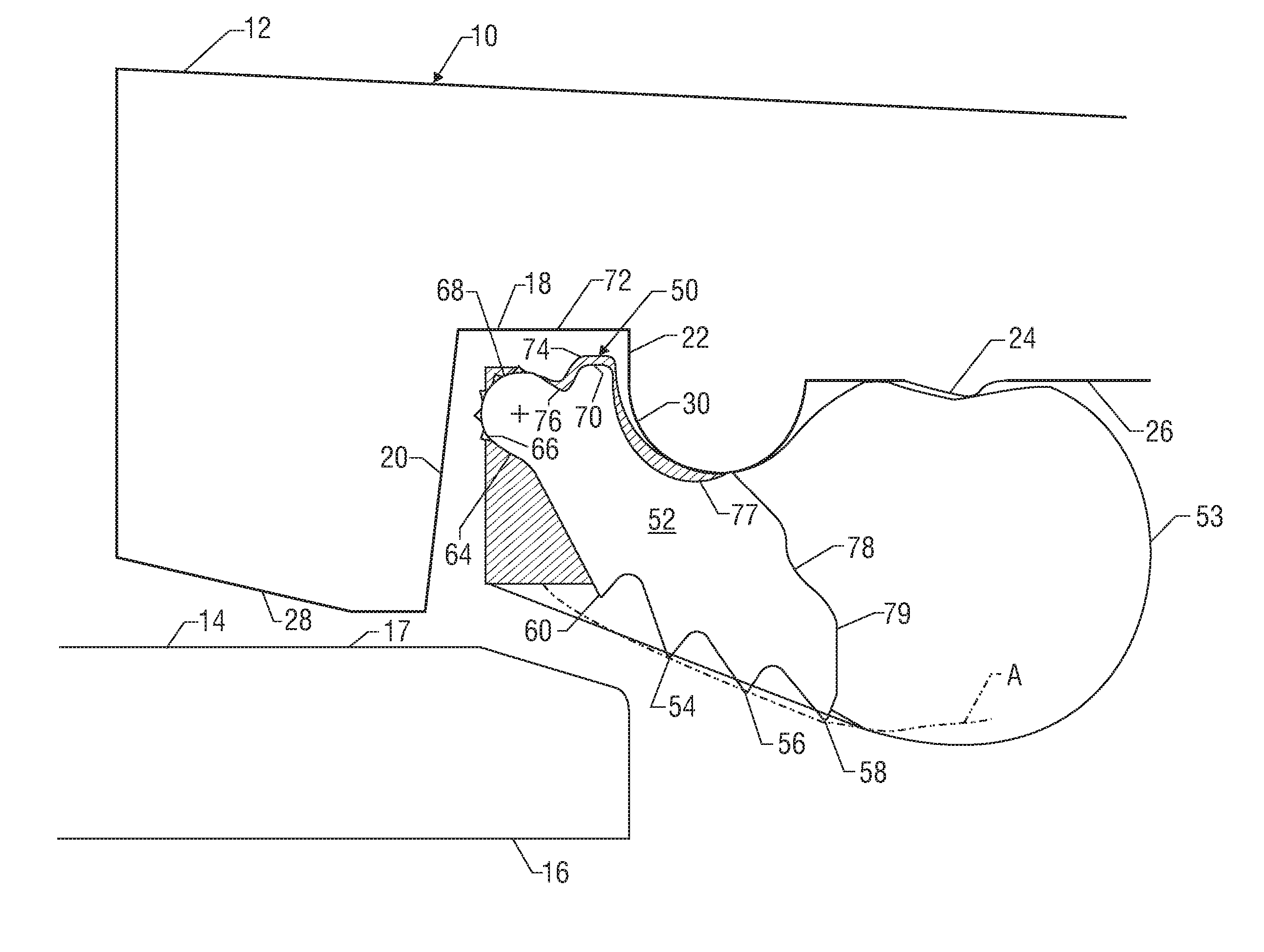
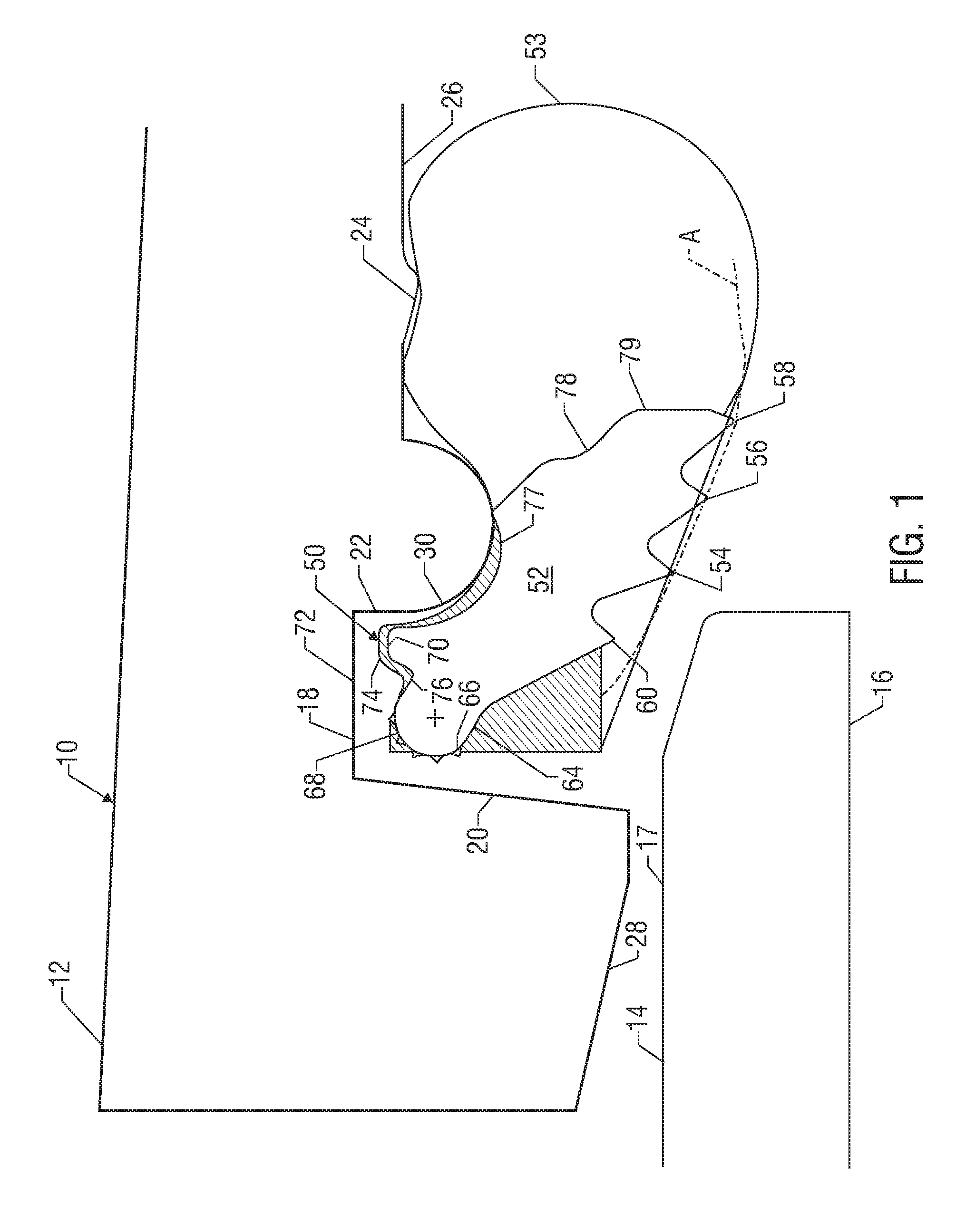
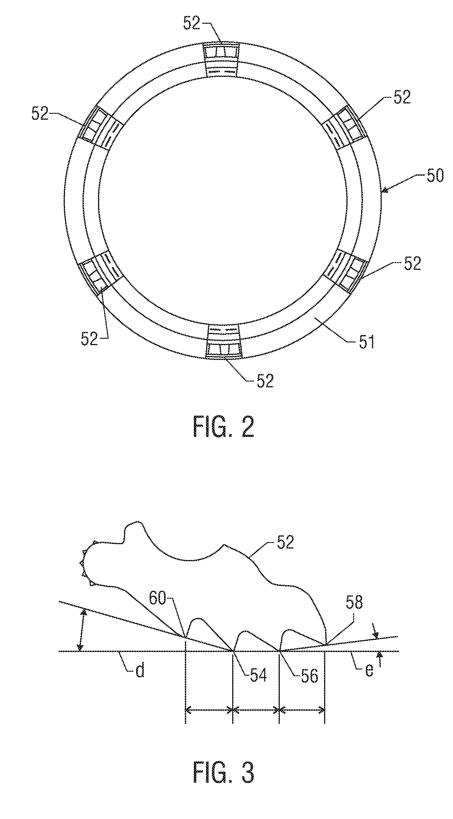
[0017] The present invention relates to devices and methods providing rugged and cost-effective gasket arrangements for pipe joints. The present invention is susceptible to embodiments of different forms. There are shown in the drawings, and herein will be described in detail, specific embodiments of the present invention with the understanding that the present disclosure is to be considered an exemplification of the principles of the invention, and is not intended to limit the invention to that illustrated and described herein. As used herein, the terms radially inward(ly) and radially outward(ly) are used with reference to the axial centerline of the tubulars (i.e., meaning pointing toward or away from the tubular centerline). The terms axially forward means in a direction toward the end of the tubular and term axially rearward means in a direction toward the middle of the tubular. Further, no particular geometry, material, or other technical limitation is implied by the term “gas...


PUM

PropertyMeasurementUnit
forward angle of declinationaaaaaaaaaa

Abstract

A novel gasket includes at least one gripping element embedded in an annular member for forming a seal between two tubulars. For tubulars having socket and spigot ends, the gripping element includes teeth for gripping an outer surface of the spigot end and a blunt tooth for contacting a front wall of the socket end. The blunt tooth rolls along the front wall during relative movement between the tubulars and can include a contacting face of a specialized geometry to adjust contact dynamics and / or roughened surfaces to increase the frictional contact between the blunt tooth and the front wall. The embedded element can also include at least four teeth arranged such that no more than two teeth normally grip the outer surface of the spigot end. One or more teeth can also include a transverse groove to enhance penetration into the outer surface of the spigot end.

Description

CROSS-REFERENCES TO RELATED APPLICATIONS [0001] This application is a continuation of U.S. patent application Ser. No. 10 / 817,674, filed Apr. 2, 2004.BACKGROUND OF THE INVENTION [0002] 1. Field of the Invention [0003] This invention relates to devices for locking joints for tubular members. More particularly, the present invention relates to gaskets for sealing and locking a socket end of one tubular to a spigot end of another tubular. [0004] 2. Description of the Prior Art [0005] Pipes joined in telescoping relationship typically have a spigot end of one pipe inserted into the socket end of the engaging pipe. The socket end has an opening large enough to receive the spigot end of the enclosed pipe. A gasket is inserted in the socket end of the enclosing pipe and prevents leakage of fluid from the joint by forming a seal between the two pipes. In many applications, a fluid under pressure flows through the pipes. This fluid pressure can produce a separating force, known as joint sepa...

Claims


Application Information

Patent Timeline
Patent Type & Authority Applications(United States)
IPC IPC(8): F16L21/00B23P19/04F16L17/00F16L21/02F16L21/08F16L27/08F16L37/084
CPCY10T29/5367F16L37/0845
Inventor WALWORTH, VAN T.HOOK, DAVID B.
Owner STAR PIPE PRODS
Why Eureka
Try Eureka