Rfid Apparatus

a radiofrequency identification and apparatus technology, applied in the field of radiofrequency identification apparatuses, can solve the problems of increasing complexity, cost and size of dual mode solutions, and not necessarily providing the optimal system level solution for an ever-increasing diversity of application areas, so as to achieve significant size or cost penalty, maximum range performance, and minimal increase in circuit complexity

Active Publication Date: 2008-01-24
NXP USA INC
View PDF10 Cites 231 Cited by
  • Summary
  • Abstract
  • Description
  • Claims
  • Application Information

AI Technical Summary

Benefits of technology

[0011]The present invention enables a single antenna solution, which solves the problem of there being inherently different properties of the antennas used for individual reader and / or tag functionality. The use of an internal generating means for generating an RF signal dependent on the incoming RF signal provides an arrangement whereby it is possible to emulate tag functionality without needing a conventional tag antenna arrangement.
[0012]Further, the invention has the advantage that a dual mode apparatus according to the invention can be implemented such that pre-existing readers do not need to be changed to ensure interoperability.
[0013]Use of the present invention can also avoid range reduction due to insufficient modulation depth; modulation depth can be achieved by appropriate control of the generation means.
[0015]Embodiments of the invention can be used to achieve maximum range performance, with minimal increase in circuit complexity, and without a significant size or cost penalty compared to a conventional single mode reader / tag system.
[0016]Additional advantages of the invention include reduced silicon area and reduced power consumption, compared to a dual mode system in which the reader and tag circuitry is separated.

Problems solved by technology

The existing RFID system concepts, based on isolated reader and tag functionality, do not necessarily provide the optimum system level solution for an ever-increasing diversity of application areas.
However, close proximity of the antennas will result in interference between the antennas.
These solutions also result in increased complexity, cost and size of the dual mode solution.

Method used


Image

  • Rfid Apparatus
  • Rfid Apparatus
  • Rfid Apparatus

Examples


first embodiment

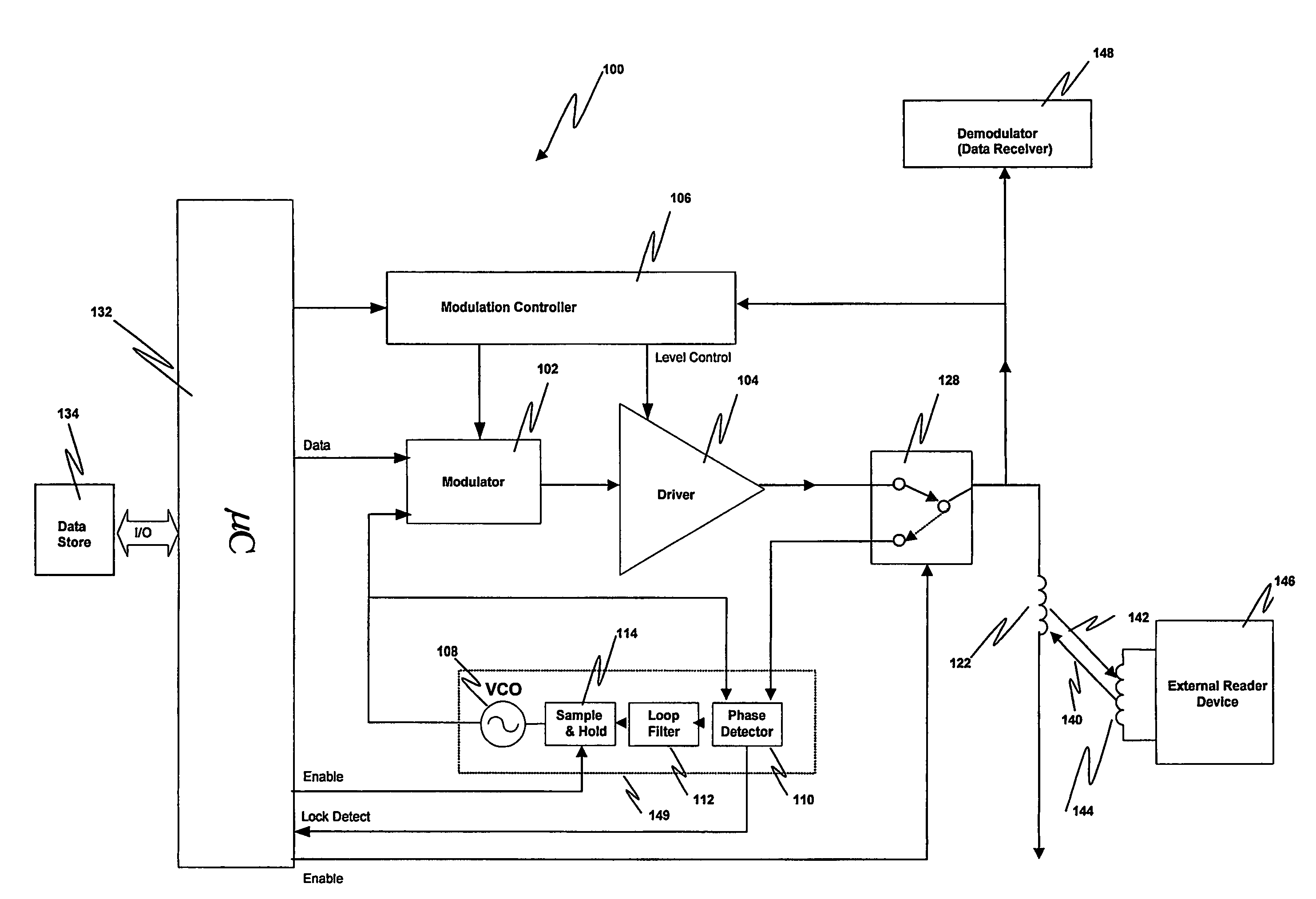
[0033]FIG. 4 is a circuit diagram of elements of the apparatus used in tag emulation mode, according to the present invention. The apparatus 100 includes a micro-controller 132, a modulator function 102, a driver function 104, an antenna 122 and a phase-locked loop 149 comprising in this embodiment a voltage controlled oscillator (VCO) 108, a phase detector 110, a loop filter 112 and preferably a sample and hold circuit 114. Although shown separately in FIGS. 3 and 4, the modulator and driver functions 102 and 104 may be comprised within the same component. Additionally the dual mode apparatus may include a switch 128, which indirectly controls the operational mode (i.e. whether reader or tag emulation) through coupling of incoming RF signal to phase lock loop mechanism and means 106 for controlling the modulation or RF signal output level. The apparatus will also have access to, whether within itself (for example as part of the microcontroller) or as part of a separate component or...

second embodiment

[0045]FIG. 5 is a circuit diagram of elements used in tag emulation mode in dual mode apparatus according to the present invention. The reference numbers of similar components to FIG. 4 have been incremented by 100, and the relevant description of those components above should be taken to apply. Further, although not illustrated, elements used during operation of the device in reader mode will be similar to those illustrated in FIG. 3 above, and the relevant description of those components above should be taken to apply.

[0046]As described above, operation of the apparatus will depend on whether the apparatus is in reader or tag emulation mode. In addition to the first embodiment, apparatus of the second embodiment additionally includes a clamp 220 and a composite loop filter and hold function 218. The composite loop filter and hold function 218 replaces the loop filter and sample & hold components in FIG. 4 of the previous embodiment.

[0047]The clamp 220 is used to reduce the risk of...


PUM


Abstract

RFID apparatus includes transmission means for transmitting an RF signal; reception means for receiving a modulated RF signal; and demodulation means for demodulating a received modulated signal. The apparatus comprises generating means for generating a RF signal dependent on an incoming RF signal, the incoming RF signal being generated by different apparatus, and the apparatus is arranged to transmit the generated RF signal such that the generated RF signal interferes with the incoming RF signal. The RFID apparatus has both the means to respond to an RF reader device, in tag emulation mode, and means to function as an RF reader device, in reader mode.

Description

FIELD OF THE INVENTION[0001]The present invention relates to radio-frequency identification (RFID) apparatus. The term “RFID” as used herein should be understood to include both traditional RFID systems, in which an RFID tag is used for identification, other systems such as near field communications (NFC) systems, and other similar systems which are for the storage and retrieval of data and / or commands, and not necessarily only for identification purposes.BACKGROUND OF THE INVENTION[0002]The growth and diversity of RFID applications is progressing at an exponential rate and now includes NFC systems. The existing RFID system concepts, based on isolated reader and tag functionality, do not necessarily provide the optimum system level solution for an ever-increasing diversity of application areas. Many of these emerging application areas may require each element within the RFID or NFC system to possess dual mode reader / tag functionality or dual activity.[0003]Several technical problems...

Claims


Application Information

Patent Timeline
Patent Type & Authority Applications(United States)
IPC IPC(8): G06K7/00G06K19/00G06K19/07
CPCG06K7/0008G06K7/10237H04B5/0062G06K19/0712G06K19/0723G06K19/0707
Inventor PITT-PLADDY, GLEN
Owner NXP USA INC
Why Eureka
Try Eureka