
Radio frequency signature augmentation system

Inactive Publication Date: 2008-01-24
THE BOEING CO
View PDF9 Cites 45 Cited by
  • Summary
  • Abstract
  • Description
  • Claims
  • Application Information

AI Technical Summary

Benefits of technology

[0010] Embodiments of the present invention simulate a variety of platforms, such as without limitation threat aircraft, with a sufficiently high fidelity level for a realistic evaluation of weapon systems. As a result, boundaries of missile performance envelopes can be evaluated against different threats with greater accuracy than is achievable with use of sub-scale platforms such as drones and without the prohibitive and infeasible costs associated with acquisition of full-scale targets such as aircraft. Also, embodiments of the present invention are able to simulate several different targets, including without limitation fixed wing and rotary wing aircraft, thereby providing weapon systems evaluators with increased flexibility over conventional testing methods. The simulated targets may include aircraft such as helicopters, fighter aircraft, bomber aircraft, ballistic missiles, land-based platforms, and maritime platforms such as ships and submarines, as desired. Advantageously, simulation performed by embodiments of the present invention includes emulation as well as augmentation.
[0011] Embodiments of the present invention augment the radiofrequency (RF) signature of a host platform, like a subscale air vehicle such as a drone or the like, to simulate the RF signature of a simulated platform, such as a full-sized aircraft or the like, with sufficient fidelity for weapon system testing, evaluation, and training (for target aircraft) and for deception of radar systems (for decoy aircraft). Any one or a combination of modulation techniques, including amplitude modulation, phase modulation, polarization modulation, and range extent modulation, suitably are used to generate an aspect-dependent signature of a desired aircraft. Further, embodiments of the present invention may program, activate / deactivate, and / or vary RF signature facets and parameters. As a result, embodiments of the present invention are able to simulate different target signatures to evaluate boundaries of missile performance envelopes unmatched by conventional techniques.
[0012] As such, embodiments of the present invention provide a signal repeater that modulates a signal received from an illuminating radar and sends back to the illuminating radar the modulated signal. Because the present invention may be embodied as a repeater, the modulated signal is sent back to the illuminating radar only when the radar signal has been received from the illuminating radar. Advantageously, this improves realism over signals that are continuously generated and transmitted toward the illuminating radar—regardless of whether the target may have been illuminated by the illuminating radar.

Problems solved by technology

As a result, evaluating and / or deceiving these types of sophisticated weapon systems have become increasingly difficult.
A lack of targets available for weapon systems evaluation exists because of practicality and cost constraints.
For example, no bomber aircraft are available in current U.S. inventories for use as targets in evaluating employment of modern weapon systems against bomber aircraft.
This lack of target assets forces weapon evaluators to use similarly-sized surplus assets and / or subscale drones that employ means for enhancing their signatures to levels representative of actual targets.
However, because of relatively high acquisition and maintenance costs, a full-size target, such as a QF-4, is available for only a small percentage of flight tests.
Moreover, because of its large and complex structure and span, a bomber offers unique challenges for missile tracking algorithms.
However, relatively small physical characteristics of available assets do not provide target signature levels and fidelity that are representative of full-sized fighter and bomber targets.
Similarly, current decoys lack sufficient signature fidelity, thereby enabling advanced enemy weapon systems to reject the decoys during battlefield engagement.
While these techniques are acceptable for crew training exercises, they are not suitable for missile evaluation purposes.
Each type of modulation produces undesired effects on the engaging missile.

Method used


Image

  • Radio frequency signature augmentation system
  • Radio frequency signature augmentation system
  • Radio frequency signature augmentation system

Examples


Embodiment Construction

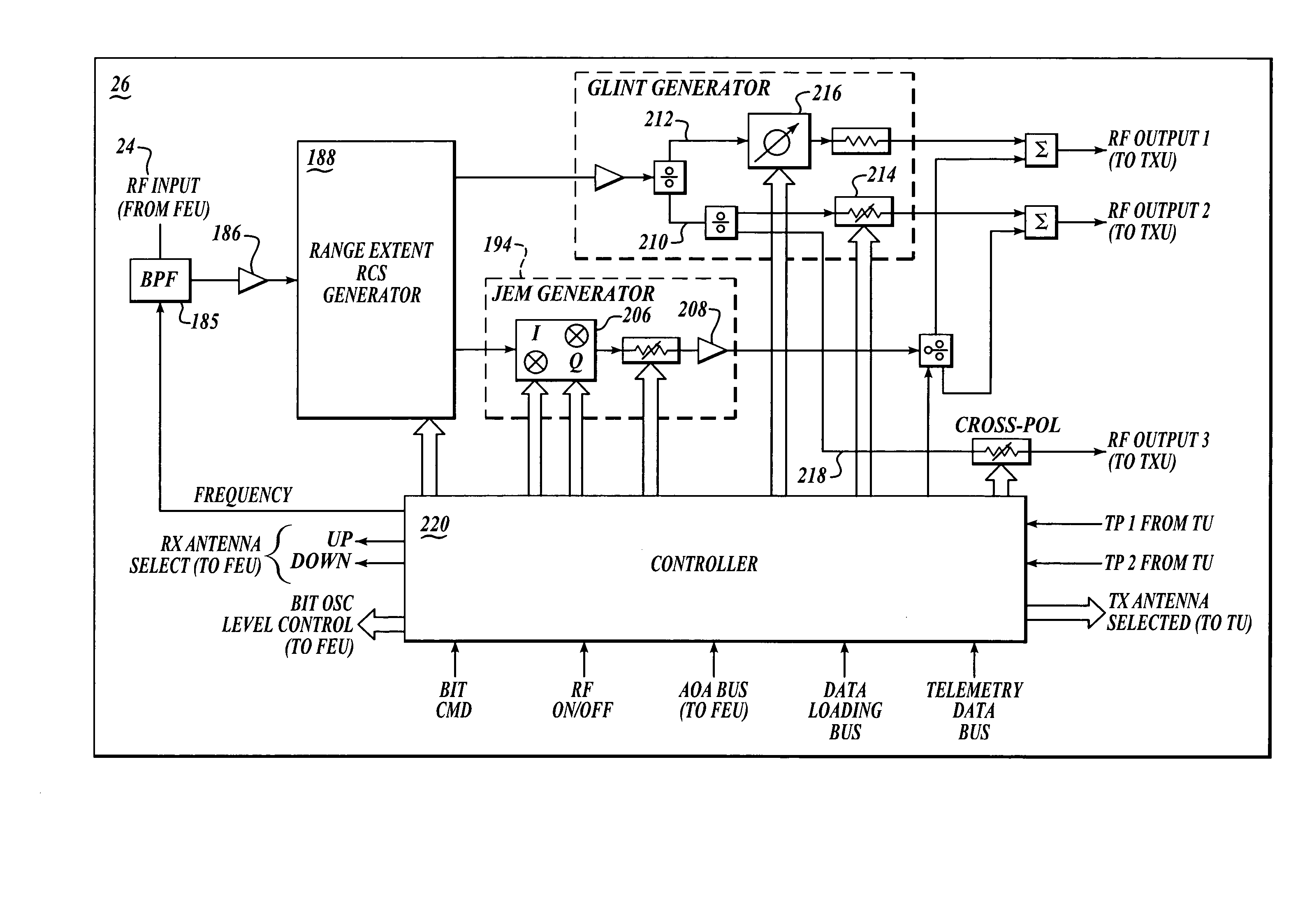
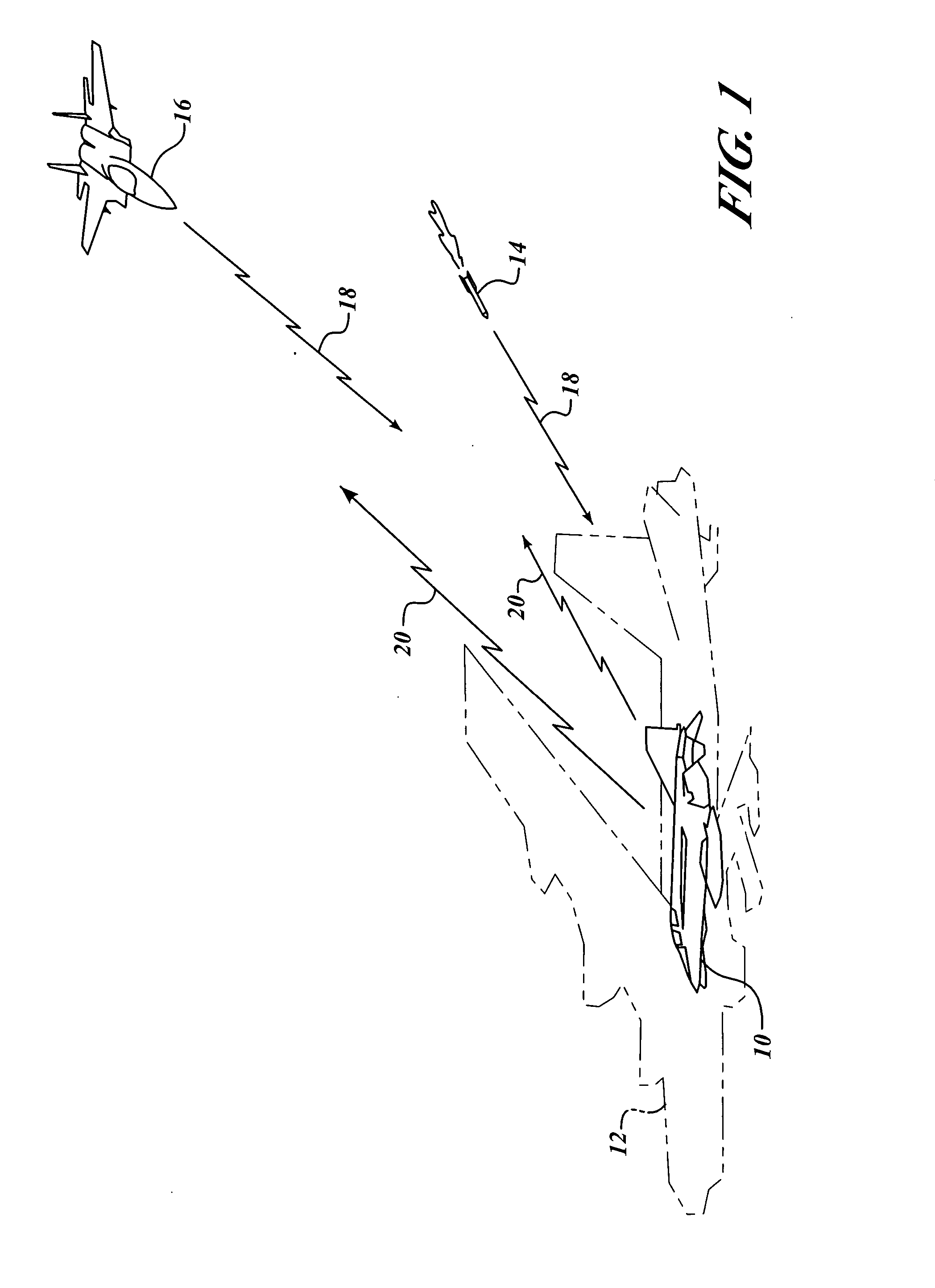
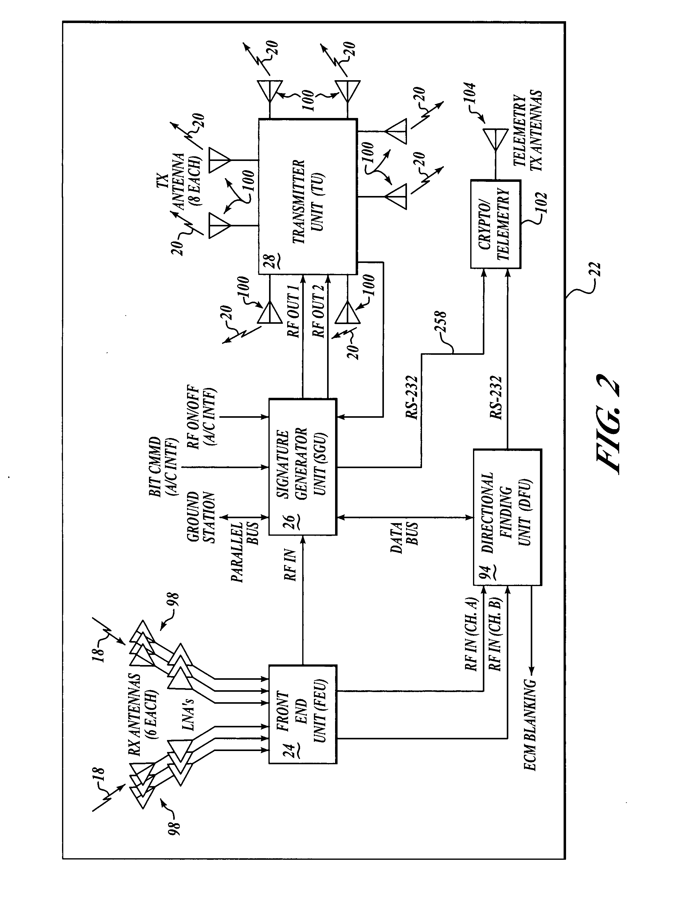
[0043] Embodiments of the present invention simulate a variety of threat platforms with a sufficiently high fidelity level for a realistic evaluation of weapon systems. Advantageously, simulation performed by embodiments of the present invention includes emulation as well as augmentation. Referring to FIG. 1 and by way of overview, embodiments of the present invention augment the radiofrequency (RF) signature of a host platform 10, such as without limitation a subscale air vehicle like a drone or the like, to simulate the RF signature of a simulated platform 12 such as without limitation a full-sized aircraft (shown in phantom) with sufficient fidelity for testing, evaluation, and training of a weapon system 14 (for target aircraft) and for deception of a radar system 16 (for decoy aircraft). Still by way of overview and given by way of non-limiting example, an incoming radar signal 18 has a polarization and is transmitted from a radar source, such as the weapon system 14 or the rad...


PUM


Abstract

Systems and methods are provided for simulating a target platform. An incoming radar signal is transmitted from a radar source and is received at a first platform. Time of the received radar signal is modulated to generate first and second range extent signals. The first range extent signal is vector modulated, and the second range extent signal is divided into a plurality of divided second range extent signals. A first of the plurality of divided second range extent signals is phase modulated. A second of the plurality of divided second range extent signals is amplitude modulated. The modulated signals are transmitted from the first platform.

Description

FIELD OF THE INVENTION [0001] The present invention relates to target signal simulation and, more specifically, to radio frequency signature augmentation. BACKGROUND OF THE INVENTION [0002] Advances in weapon systems technology have enabled some weapon systems to discriminate targets based on target signatures. As a result, evaluating and / or deceiving these types of sophisticated weapon systems have become increasingly difficult. [0003] Various methods are currently used to evaluate weapon systems. These evaluation methods include computer modeling, hardware-in-the-loop (HIL), and flight testing. Currently, the evaluation method that is chosen for use depends on the development stage of the weapon systems to be evaluated. However, only during flight tests are a missile's kinematics, target tracking, and counter electronic countermeasures (counter ECM) performance capabilities fully exercised and evaluated. [0004] A lack of targets available for weapon systems evaluation exists becau...

Claims


Application Information

Patent Timeline
IPC IPC(8): G01S7/40
CPCG01S7/024G01S2007/4095G01S7/4052G01S7/38G01S7/4095
Inventor SVY, KOSALEASTMAN, GEORGE A.LEE, JAMES D.
Owner THE BOEING CO
Learn More