Gas bubble-generating agent

a gas bubble and generating agent technology, applied in the field can solve the problems of limited effect of gas bubble generating agents of conventional techniques as contrast medium or blocking agents, and inability to selectively generate gas bubbles in the vicinity of sites

Inactive Publication Date: 2008-01-24
HITACHI LTD
View PDF4 Cites 9 Cited by
  • Summary
  • Abstract
  • Description
  • Claims
  • Application Information

AI Technical Summary

Problems solved by technology

Thus, it is impossible to generate gas bubbles selectively at given regions in the vicinity of the site to which the gas bubble-generating agent has been administered.
Accordingly, the effect of a gas bubble-generating agent of a conventional technique as a contrast medium or blocking agent is limited.

Method used


Image

  • Gas bubble-generating agent
  • Gas bubble-generating agent
  • Gas bubble-generating agent

Examples


example 1

Preparation of Gas Bubble-Generating Agent

[0072]The ingredients shown below were maintained at 4° C. and mixed, and the resulting mixture was homogenized with an Ultra Turrax T25 (Janke & Kunkel, Staufen, Germany) at 9,500 rpm for 1 minute while slowly adding 20 ml of phosphate buffer (pH: 7.4).

TABLE 1Glycerol2.0 gα-Tocopherol0.02 g Cholesterol0.1 gPhosphatidyl choline1.0 gPerfluoropentane0.1 g2H,3H-perfluoropentane0.1 gMPEG-2000-DSPE0.01 g 

[0073]The chemical structure of MPEG-2000-DSPE is shown below.

[0074]The resulting emulsion was subjected to high-pressure emulsification in an Emulsiflex-C5 (Avestin, Ottawa, Canada) at 20 MPa for 10 minutes, the resultant was centrifuged at 10,000 G for 15 minutes, the residue was removed, and filtration was carried out using a 0.1-μm membrane filter to obtain a substantially transparent microparticle dispersion. The dispersion was refrigerated until the time of use, and the temperature was raised to room temperature immediately before use. The ...

example 2

Preparation of Gas Bubble-Generating Agent Using a Polymer having a Functional Group

[0083]The ingredients shown below were maintained at 4° C. and mixed, and the resulting mixture was homogenized with an Ultra Turrax T25 (Janke & Kunkel, Staufen, Germany) at 9,500 rpm for 1 minute while slowly adding 20 ml of phosphate buffer (pH: 7.4).

TABLE 2Glycerol2.0 gα-Tocopherol0.02 g Cholesterol0.1 gPhosphatidyl choline1.0 gPerfluoropentane0.1 g2H,3H-perfluoropentane0.1 gMPEG-2000-DSPE0.007 g MPEG-2000-DSPE-MA0.003 g 

[0084]The chemical structure of MPEG-2000-DSPE-MA is shown below.

[0085]The resulting emulsion was subjected to high-pressure emulsification in an Emulsiflex-C5 (Avestin, Ottawa, Canada) at 20 MPa for 10 minutes, the resultant was centrifuged at 10,000 G for 15 minutes, the residue was removed, and filtration was carried out using a 0.1-μm membrane filter to obtain a substantially transparent microparticle dispersion. The dispersion was refrigerated until the time of use, and the ...

example 3

Ultrasonic Applicator

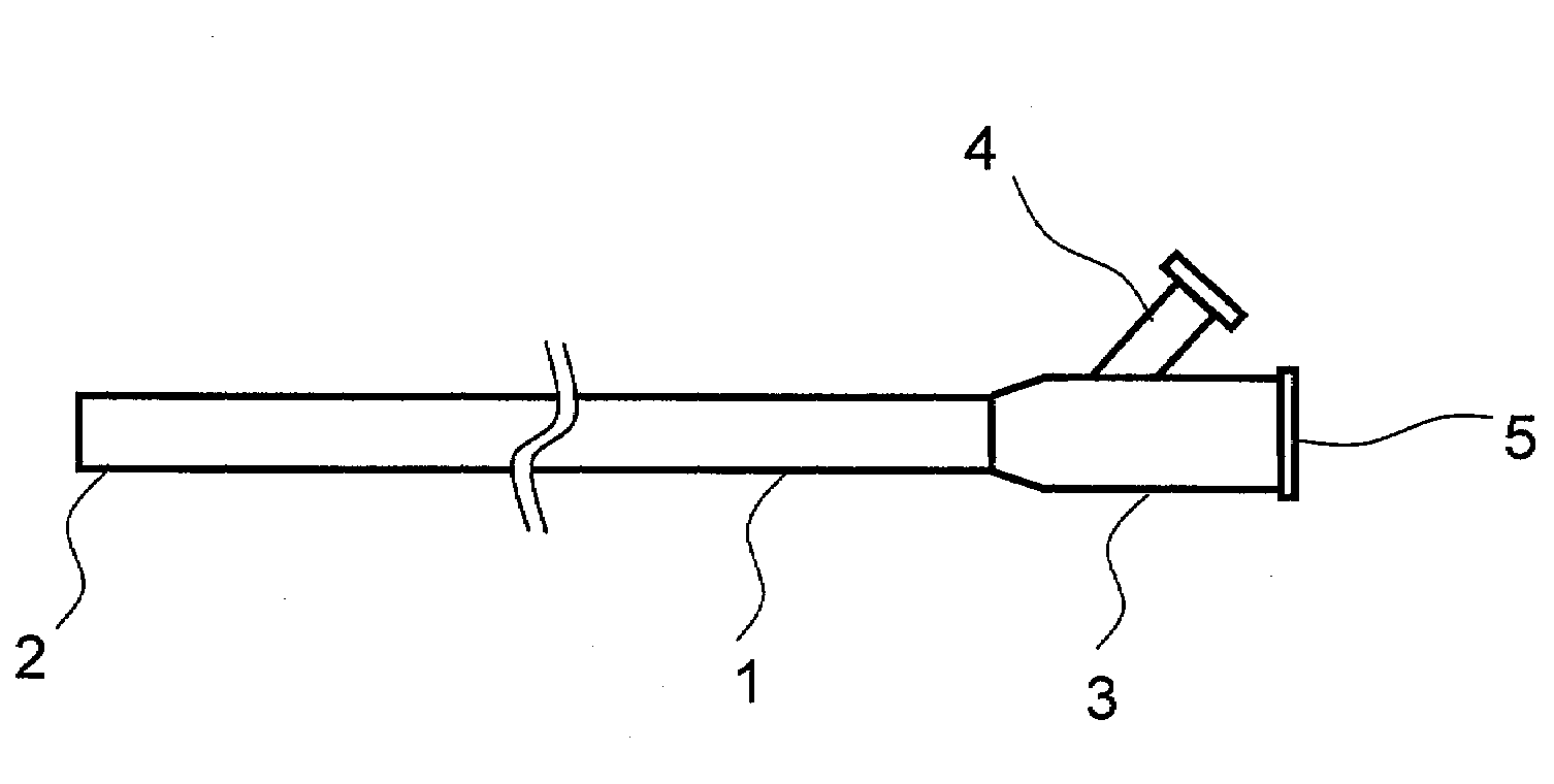
[0086]An example of an ultrasonic applicator used in combination with the gas bubble-generating agent of the present invention is described with reference to FIGS. 5, 6, and 7. FIG. 5 shows the structure of a catheter used for administering a gas bubble-generating agent to the affected area. FIG. 5(a) shows an appearance of a catheter, which comprises a catheter body1, a catheter end 2, and a catheter base 3. The catheter base 3 comprises a gas bubble-generating agent-introduction port 4 and a guidewire port 5. At the time of use, a reservoir containing a gas bubble-generating agent is connected to the gas bubble-generating agent-introduction port 4, and the gas bubble-generating agent is pressurized using a pressurization means and discharged from the end 2. FIG. 5(b) shows a cross-section of the catheter body 1. As shown in this figure, the catheter body 1 comprises: a channel for a gas bubble-generating agent, i.e., a channel 6 that introduces the gas bubble-...


PUM


Abstract

This invention provides a gas bubble-generating agent that can be used as a contrast medium or a blocking agent in vivo. Such gas bubble-generating agent is produced by a method for producing a gas bubble-generating agent comprising the following steps of: (a) preparing a mixed solution of an amphiphilic substance, an amphiphilic substance comprising a water-soluble polymer chemically bound thereto, a hardly water-soluble substance having a boiling point of lower than 60° C. at atmospheric pressure, and a physiologically acceptable isotonic solution; (b) pressurizing the mixed solution; and (c) centrifuging the mixed solution after the step of pressurization, wherein a molar concentration of the amphiphilic substance in the mixed solution prepared in step (a) is 10 times or more higher than that of the amphiphilic substance comprising a water-soluble polymer chemically bound thereto.

Description

CLAIM OF PRIORITY[0001]The present application claims priority from Japanese application JP 2006-195666 filed on Jul. 18, 2006, the content of which is hereby incorporated by reference into this application.BACKGROUND OF THE INVENTION[0002]1. Field of the Invention[0003]The present invention relates to a gas bubble-generating agent that is in a liquid state at low temperatures and that evaporates and generates gas bubbles in response to temperature increase or physical stimulation, a method for producing the same, and a therapeutic method using such gas bubble-generating agent.[0004]2. Background Art[0005]If gas bubbles can be generated in vivo, blood vessels can be blocked. This is effective as a therapeutic means for diseases that can be treated by blocking nutrient vessels, such as malignant neoplasm and hysteromyoma. Such gas bubbles can also be used as a contrast medium for diagnostic imaging apparatuses such as ultrasonic diagnostic system or MRI diagnostic systems.[0006]As a ...

Claims


Application Information

Patent Timeline
Patent Type & Authority Applications(United States)
IPC IPC(8): A61B8/00
CPCA61B5/4839A61K41/0033A61B8/481A61P35/00
Inventor KAWABATA, KENICHIHIRATA, KOJISASAKI, KAZUAKI
Owner HITACHI LTD
Why Eureka
Try Eureka