Automotive diesel exhaust HC dosing valve for use with diesel particulate filter systems

a technology of diesel exhaust and dosing valve, which is applied in the direction of engines, mechanical equipment, machines/engines, etc., can solve the problems of reducing engine performance, generating particulates (soot), and not being effective in reducing no/sub>x/sub>,

Inactive Publication Date: 2008-01-31
CONTINENTAL AUTOMOTIVE SYST INC
View PDF11 Cites 14 Cited by
  • Summary
  • Abstract
  • Description
  • Claims
  • Application Information

AI Technical Summary

Benefits of technology

[0009] In view of the foregoing, it is an object of the invention to provide a dosing valve assembly for an internal combustion engine that eliminates the need for water cooling of the dosing valve.
[0012] In accordance with aspects of the invention, a dosing valve assembly is disclosed for administering a reducing agent, such as for example, diesel fuel, into an exhaust stream from an internal combustion engine upstream of a catalytic converter and DPF. The dosing valve assembly comprises a control valve coupled to a source of the reducing agent, a delivery valve constructed and arranged for coupling to the exhaust stream at a location upstream of the catalytic converter and DPF to enable a quantity of reducing agent to be administered into the exhaust stream, and an elongated conduit connecting the control valve and delivery valve for fluidly communicating the reducing agent from the control valve to the delivery valve. The disclosed arrangement enables the control valve to be displaced from the delivery valve and away from the high temperature environment proximal to the exhaust stream.

Problems solved by technology

These converters virtually eliminate the typical odors associated with diesel engines, and reduce visible particulates, however they are not effective in reducing NOx due to excess oxygen in the exhaust gas stream.
Another problem prevalent with diesel engines is the generation of particulates (soot).
A clogged DPF can create undesired backpressure on the exhaust stream and thereby reduce engine performance.
However, water cooling requires specialized plumbing and additional components that ultimately increase costs and reduce reliability.

Method used


Image

  • Automotive diesel exhaust HC dosing valve for use with diesel particulate filter systems
  • Automotive diesel exhaust HC dosing valve for use with diesel particulate filter systems
  • Automotive diesel exhaust HC dosing valve for use with diesel particulate filter systems

Examples


Embodiment Construction

[0019] Embodiments of the invention will be described with reference to the accompanying drawing figures wherein like numbers represent like elements throughout. Before embodiments of the invention are explained in detail, it is to be understood that the invention is not limited in its application to the details of the examples set forth in the following description or illustrated in the figures. The invention is capable of other embodiments and of being practiced or carried out in a variety of applications and in various ways. Also, it is to be understood that the phraseology and terminology used herein is for the purpose of description and should not be regarded as limiting. The use of “including,”“comprising,” or “having” and variations thereof herein is meant to encompass the items listed thereafter and equivalents thereof as well as additional items.

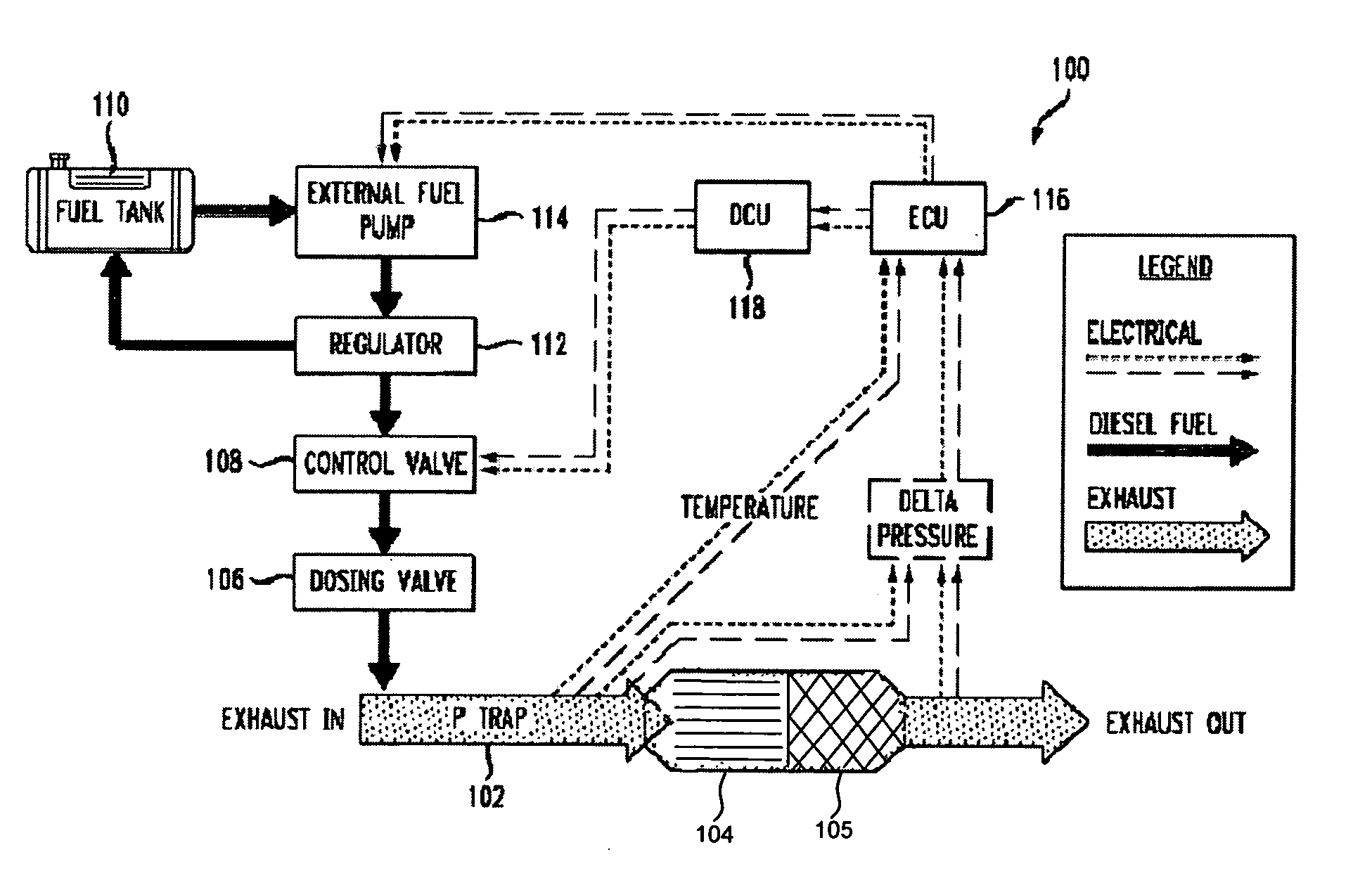
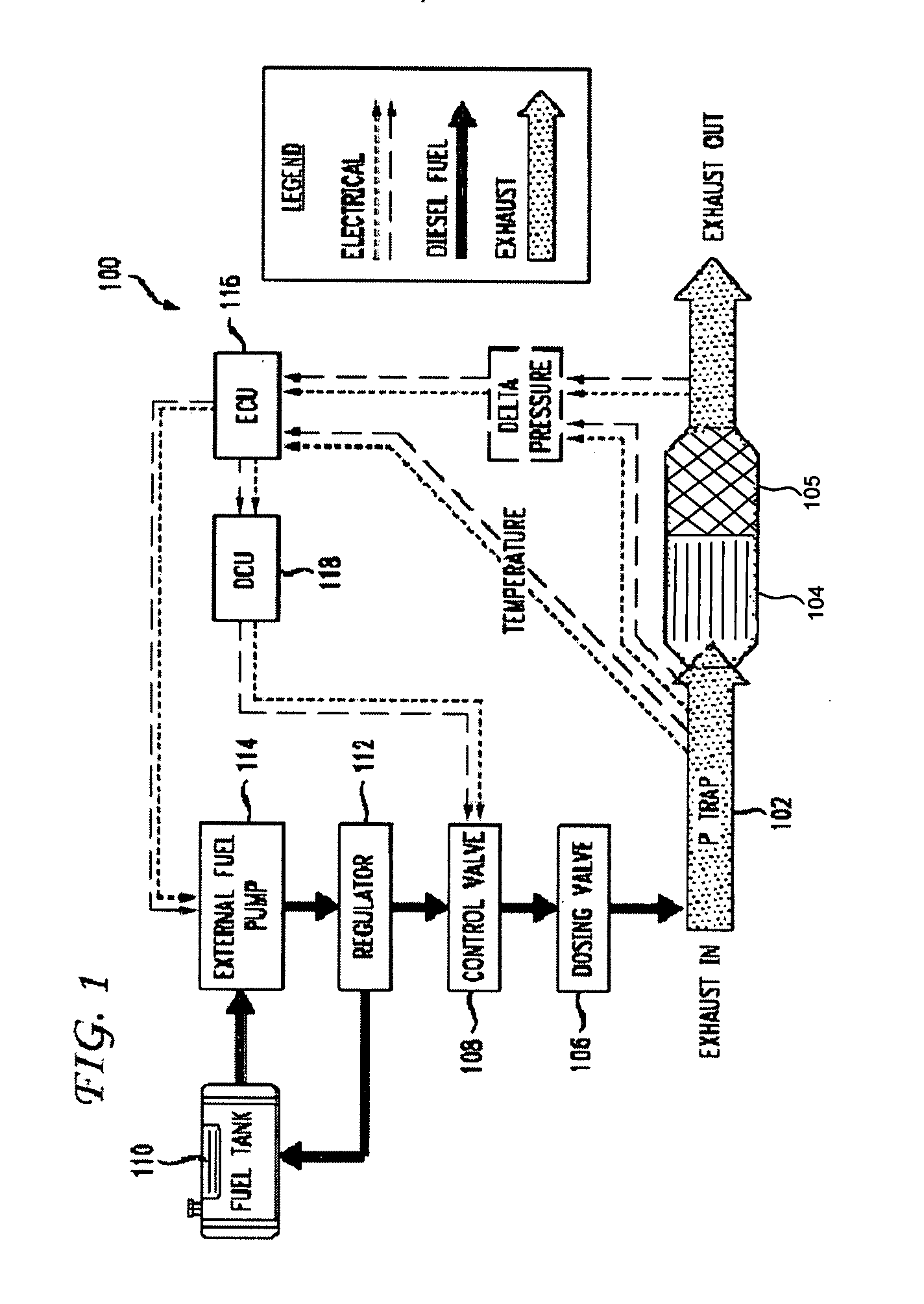
[0020] Referring to FIG. 1, there is depicted a system schematic of an exemplary dosing system 100. Exhaust from a diesel engine ...


PUM


Abstract

A dosing valve assembly is disclosed for administering a reducing agent into an exhaust stream from an internal combustion engine upstream of a catalytic converter and diesel particulate filter. The dosing valve assembly includes a control valve coupled to a source of reducing agent, a delivery valve constructed and arranged for coupling to the exhaust stream to enable a quantity of reducing agent to be administered into the exhaust stream, and an elongated conduit connecting the control valve and delivery valve for fluidly communicating reducing agent from the control valve to the fuel delivery valve. The disclosed arrangement enables the control valve to be displaced from the delivery valve and thus away from the high temperature environment proximal to the exhaust stream.

Description

CROSS REFERENCE TO RELATED APPLICATIONS [0001] This application is a continuation-in-part and claims the benefit of U.S. application Ser. No. 11 / 504,148, filed Aug. 15, 2006, which claims the benefit of U.S. Provisional Application Ser. No. 60 / 708,195, filed Aug. 15, 2005, both entitled “Automotive Diesel Exhaust HC Dosing Valve,” the contents of which are hereby incorporated by reference herein. [0002] This application further claims the benefit of U.S. Provisional Application Ser. No. 60 / 828,305, filed Oct. 5, 2006, entitled “Diesel Particulate Filter Systems,” the contents of which are hereby incorporated by reference herein.FIELD OF THE INVENTION [0003] The present invention relates generally to a system for reducing particulates and nitric oxide (NOx) emissions by diesel engines, and more particularly, to a novel hydrocarbon (HC) dosing valve system that eliminates the requirement for water cooling in a high temperature environment. BACKGROUND OF THE INVENTION [0004] Hydrocarbo...

Claims


Application Information

Patent Timeline
Patent Type & Authority Applications(United States)
IPC IPC(8): F01N3/10
CPCF01N3/0821F01N3/2066Y02T10/24F01N2610/03F01N2610/1453F01N3/36Y02T10/12
Inventor BUGOS, STEPHENHORNBY, MICHAEL J.
Owner CONTINENTAL AUTOMOTIVE SYST INC
Why Eureka
Try Eureka