System and Method for Diagnostic of Low Pressure Exhaust Gas Recirculation System and Adapting of Measurement Devices

a low-pressure exhaust gas recirculation and measurement device technology, applied in the direction of electrical control, process and machine control, instruments, etc., can solve the problems of reducing the ability to accurately control the hp and/or lp egr, degrading estimation, and aging, so as to improve the robustness and/or durability, accurately control, and improve the effect of reliability and/or durability

Active Publication Date: 2008-01-31
FORD GLOBAL TECH LLC
View PDF20 Cites 82 Cited by
  • Summary
  • Abstract
  • Description
  • Claims
  • Application Information

AI Technical Summary

Benefits of technology

[0001]Diesel engines may use re-ingested burnt exhaust gases to increase fuel economy and reduce emissions. For example, an exhaust gas recirculation (EGR) system may be used to recirculate exhaust gases from the exhaust manifold to the intake manifold. Such operation can displace fresh air and lower oxygen concentration in the cylinder, as well as reduce formation of NOx during combustion.
[0004]At least some of the above issues may be addressed by a system for a diesel engine having an intake manifold and an exhaust manifold, comprising: a turbocharger between the intake and exhaust manifolds of the engine; a low pressure exhaust gas recirculation system with a first end coupled to the exhaust manifold downstream of the turbocharger and a second end couple to the intake manifold upstream of the turbocharger, said low pressure exhaust gas recirculation having a first valve coupled thereto for regulating flow; a high pressure exhaust gas recirculation system with a first end coupled to the exhaust manifold upstream of the turbocharger and a second end coupled to the intake manifold downstream of the turbocharger, said high pressure exhaust gas recirculation having a second valve coupled thereto for regulating flow; a first mass airflow sensor coupled in the engine intake manifold upstream of said second end of said low pressure exhaust gas recirculation system; and a control system configured to diagnose the degradation of said first mass airflow sensor. In this way, it is possible to identify degraded operation of the sensor and take corrective action, if necessary.
[0006]In this way, the degradation of a MAF sensor can be diagnosed so that the control of dual EGR system may be monitored to improve robustness and / or durability.
[0007]In another embodiment, the disclosed approaches can make it possible to detect leakages or blockages of the low pressure EGR loop, and thus degradation of an EGR system can be provided.
[0008]In yet another example, a control system can provided which adapts to degradation of a MAF sensor, such as an aging effect. In this way, the EGR flows in the dual EGR system can be more accurately controlled even in the presence of sensor degradation. Thus, it is possible to provide robust control of both EGR systems by providing accurate estimation of EGR flow via adaptation of degraded MAF sensor performance.

Problems solved by technology

However, over time, the sensor may degrade or age, thus reducing the ability to accurately control the HP and / or LP EGR.
As such, degraded estimation, and thus control, of the HP and LP EGR systems can result.

Method used


Image

  • System and Method for Diagnostic of Low Pressure Exhaust Gas Recirculation System and Adapting of Measurement Devices
  • System and Method for Diagnostic of Low Pressure Exhaust Gas Recirculation System and Adapting of Measurement Devices
  • System and Method for Diagnostic of Low Pressure Exhaust Gas Recirculation System and Adapting of Measurement Devices

Examples


Embodiment Construction

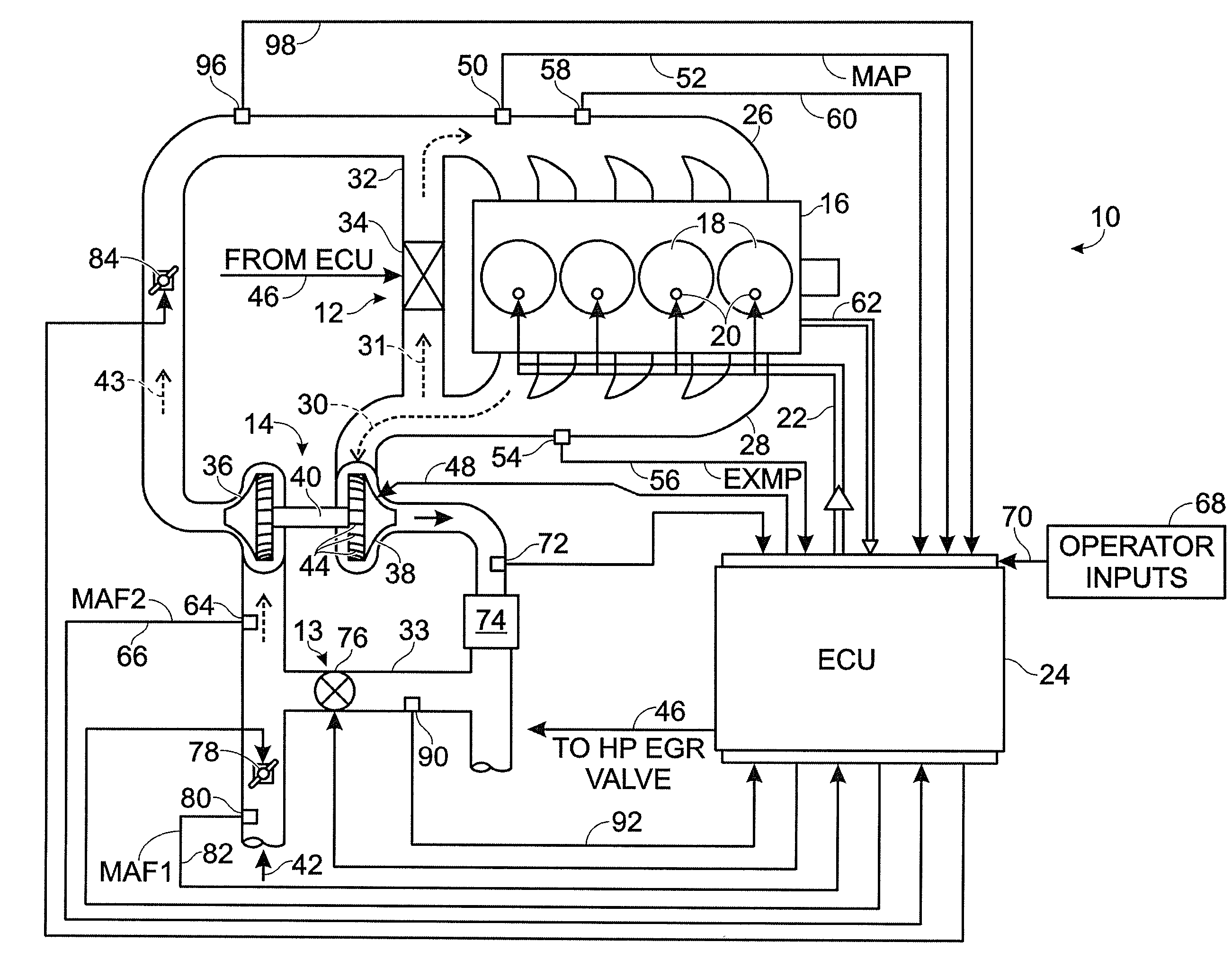
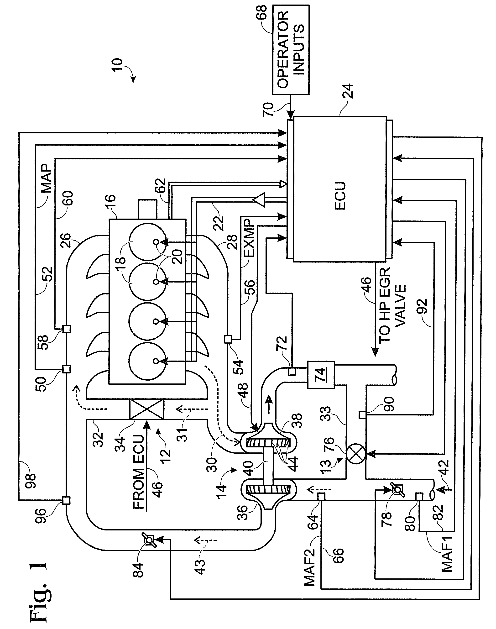
[0023]Turning first to FIG. 1, there is shown a simplified schematic diagram of a compression ignition engine system 10 equipped with a high pressure and low pressure exhaust gas recirculation (EGR) system (12 and 13, respectively) and a variable geometry turbocharger (VGT) 14. A representative engine block 16 is shown having four combustion chambers 18, although more or fewer cylinders may be used if desired. Each of the combustion chambers 18 includes a direct-injection fuel injector 20. The duty cycle of the fuel injectors 20 is determined by the engine control unit (ECU) 24 and transmitted along signal line 22. Air enters the combustion chambers 18 through the intake manifold 26, and combustion gases are exhausted through the exhaust manifold 28 in the direction of arrow 30.

[0024]To reduce the level of NOx emissions, the engine is equipped with an EGR system. The EGR system includes a high pressure (HP) EGR system 12, which comprises a conduit 32 connecting the exhaust manifold ...


PUM


Abstract

A system for a diesel engine having an intake manifold and an exhaust manifold, comprises a turbocharger between the intake and exhaust manifolds of the engine; a low pressure exhaust gas recirculation system with a first end coupled to the exhaust manifold downstream of the turbocharger and a second end couple to the intake manifold upstream of the turbocharger, said low pressure exhaust gas recirculation having a first valve coupled thereto for regulating flow; a high pressure exhaust gas recirculation system with a first end coupled to the exhaust manifold upstream of the turbocharger and a second end coupled to the intake manifold downstream of the turbocharger, said high pressure exhaust gas recirculation having a second valve coupled thereto for regulating flow; a first mass airflow sensor coupled in the engine intake manifold upstream of an inlet of said second end of said low pressure exhaust gas recirculation system; and a control system configured to diagnose the degradation of said first mass airflow sensor.

Description

BACKGROUND AND SUMMARY [0001]Diesel engines may use re-ingested burnt exhaust gases to increase fuel economy and reduce emissions. For example, an exhaust gas recirculation (EGR) system may be used to recirculate exhaust gases from the exhaust manifold to the intake manifold. Such operation can displace fresh air and lower oxygen concentration in the cylinder, as well as reduce formation of NOx during combustion.[0002]In some engine configurations that have a turbocharger, both a low pressure and high pressure EGR system may be used. For example, a high pressure (HP) EGR loop from the exhaust manifold (upstream of the turbine of turbocharger) to the intake manifold (downstream of the compressor of the turbocharger), may be used. In addition, a low pressure (LP) loop from downstream of the turbine to upstream of the compressor may also be used. See, for example, U.S. Pat. No. 6,820,599.[0003]The inventors herein have recognized several disadvantages with such an approach. Specificall...

Claims


Application Information

Patent Timeline
Patent Type & Authority Applications(United States)
IPC IPC(8): F02B29/04F02B33/44G01M99/00
CPCF02B3/06Y02T10/47F02D23/02F02D41/0072F02D41/0275F02D41/029F02D41/187F02D41/222F02M25/0707F02M25/0709F02M25/0713F02M25/0718F02M25/0735F02M25/0744F02M25/0754Y02T10/144F02B37/00F02M26/05F02M26/06F02M26/10F02M26/15F02M26/30F02M26/38F02M26/47Y02T10/12Y02T10/40
Inventor BARBE, DAVIDVAN NIEUWSTADT, MICHIEL J.UPADHYAY, DEVESH
Owner FORD GLOBAL TECH LLC
Why Eureka
Try Eureka