Heat exchanger framework

a heat exchanger and tubular technology, applied in indirect heat exchangers, lighting and heating apparatus, nuclear elements, etc., can solve the problems of metal pitting corrosion, eventual tube failure, and down time of steam generators, so as to prevent the distortion and sagging of tubes, facilitate the drainage of water, and prevent the formation of water collecting

Inactive Publication Date: 2008-01-31
THE BABCOCK & WILCOX CO
View PDF8 Cites 7 Cited by
  • Summary
  • Abstract
  • Description
  • Claims
  • Application Information

AI Technical Summary

Problems solved by technology

The retention of water in the tubes after a steam generator has been shutdown, if unremoved, will lead to metal pitting corrosion and eventual tube failure if their walls become too thin as a result of the corrosion.
Such an event is very costly since it requires the replacement of the weakened or failed tubes thereby resulting in down time of the steam generator.
Pitting corrosion is generally of greater concern than uniform corrosion because it is more difficult to detect and protect against.
Corrosion products often cover the pits, making them difficult to identify.
Apart from localized loss of thickness at the tube metal surface, corrosion pits can also be harmful by acting as stress risers.
An extremely corrosive microenvironment typically forms within a corrosion pit that varies considerably from the bulk corrosive environment.
This corrosive microenvironment can hasten growth of pits once initially formed.
The corrosion problem is exacerbated at locations where attachment welds are made to the heat exchanger tubing, such as with the supports used to maintain the tubes and tube rows of a heat exchanger tube bank in coplanar spaced-apart and parallel relation.
The heat affected zones of the attachment welds are prone to pitting corrosion.
Weld attachments are also known to restrict the thermal expansion and contraction of the tubing and thus cause it to distort or sag, such that low spots are formed in the horizontal runs of the tubing.
These low spots collect water after the steam generator is shutdown and are susceptible to pitting corrosion.

Method used


Image

  • Heat exchanger framework
  • Heat exchanger framework
  • Heat exchanger framework

Examples


Embodiment Construction

[0017]Reference will hereinafter be made to the accompanying drawings wherein like reference numerals throughout the various figures denote like elements.

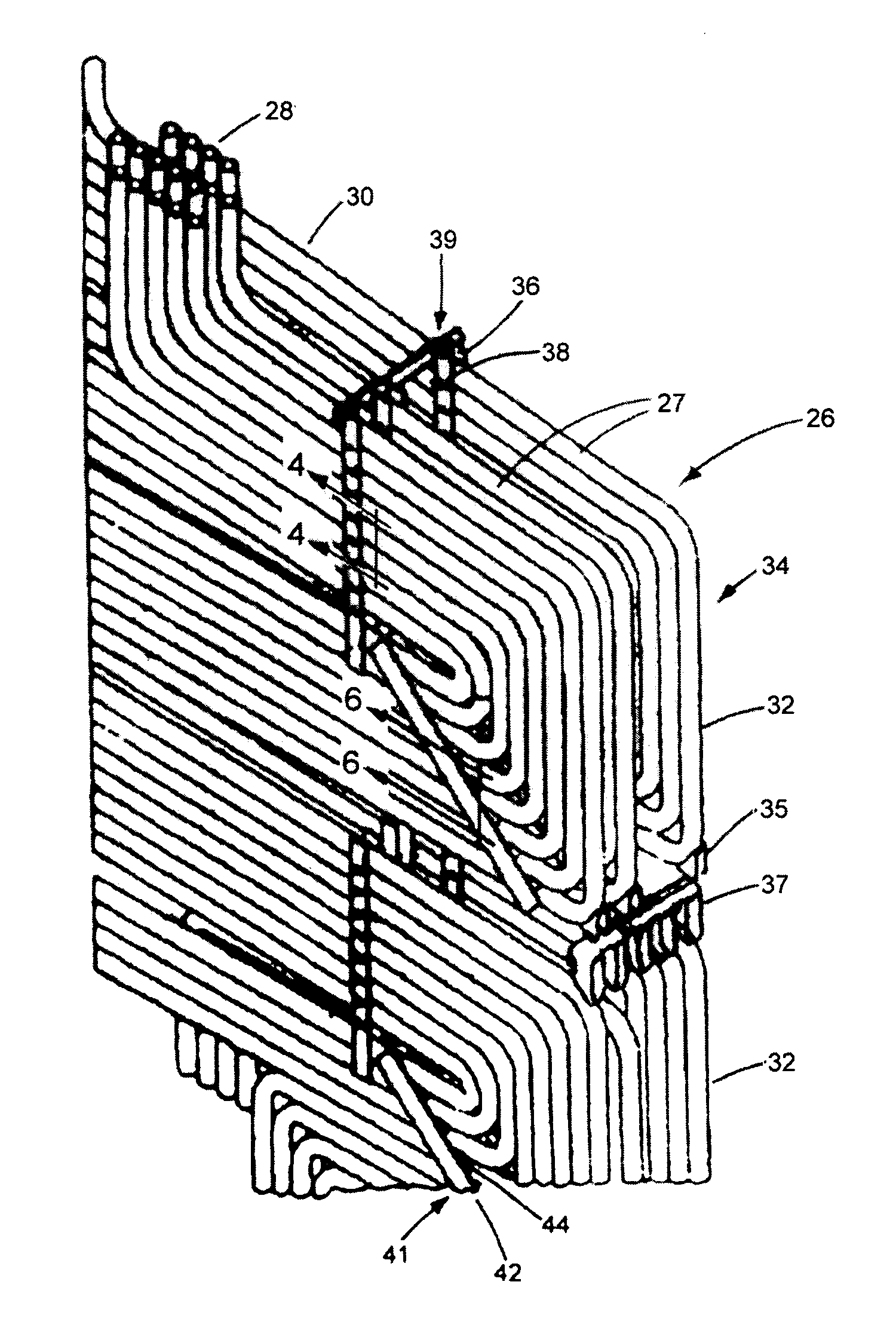
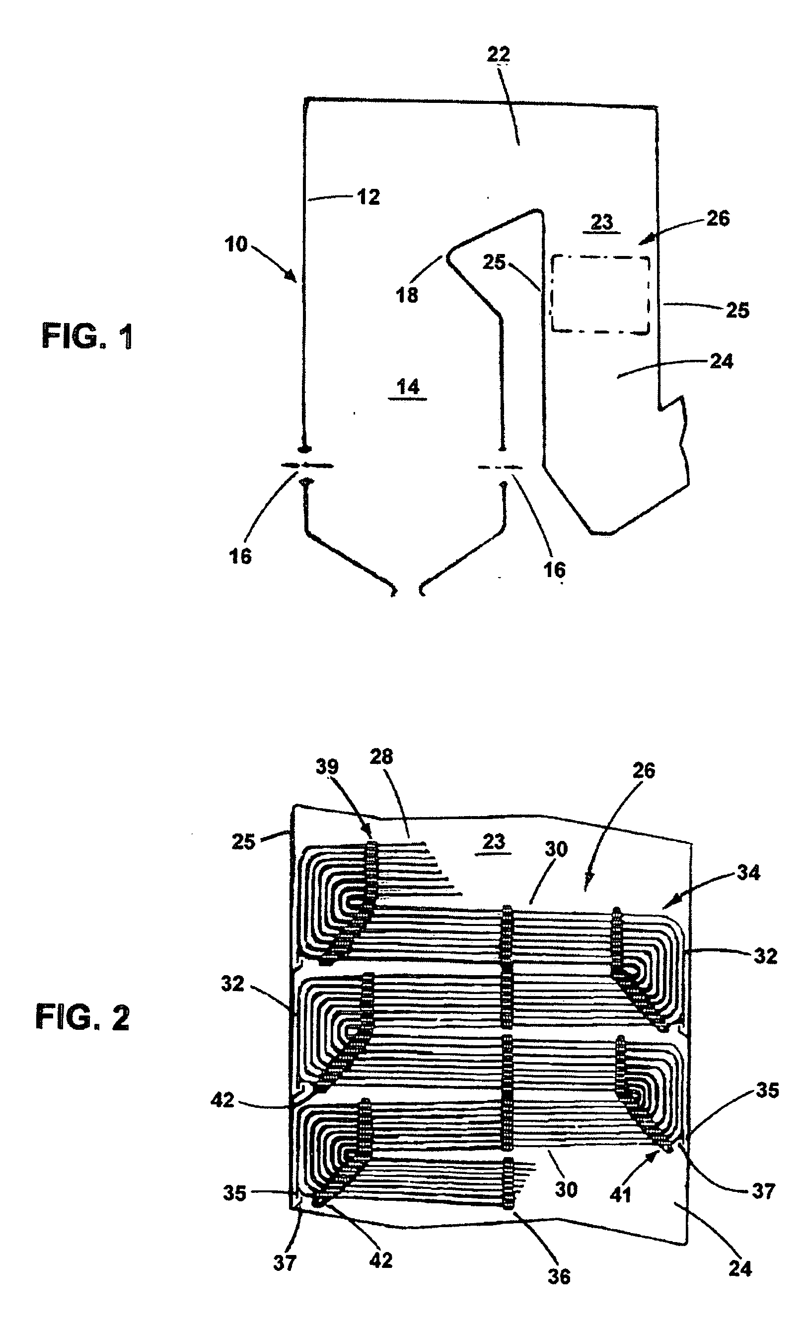
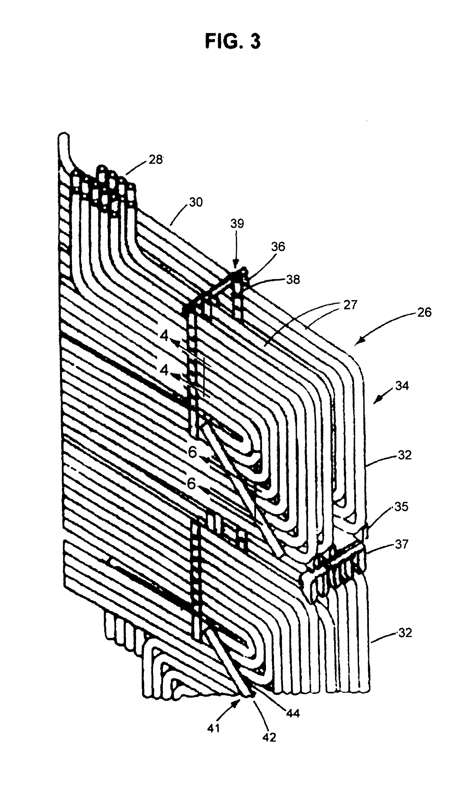
[0018]Referring to FIG. 1, there is shown a steam generator 10 including water cooled tubular walls 12 that define a furnace chamber or combustion space 14 to which a fuel and air mixture is supplied by burners as schematically shown at 16. After combustion has been completed in the furnace chamber 14, the hot gases flow upwardly and around the furnace chamber nose portion 18, and across through the horizontal section 22 of the convection passageway 23, and thence downwardly through the vertical section 24 of the convection passageway 23 which is defined by walls 25 and includes a heat exchanger such as the primary superheater 26. Usually, the gases leaving the vertical section 24 of the convection passageway 23 flow through an air heater, not shown, and thence through a gas clean-up system, not shown, and are thereafter discharged...


PUM


Abstract

A structural framework for supporting the heat exchanger of a steam generator, the former being comprised of serpentine tubes having sloped segments to facilitate the drainage of water from the heat exchanger when the steam generator is shutdown. The structural framework includes paired groups of vertically and diagonally extending first support members contiguously straddling the sloped-tube segments. The paired first support members are rigidly connected by second support members which extend between adjacent sloped-tube segments. The structural framework preserves the spacing between the sloped-tube segments and prevents direct contact between adjoining tube surfaces, but is not attached to the straddled tube segments and, thus, provides a tube supporting fit that is loose enough to permit the tubes to move freely due to expansion and contraction at different rates from that of the structural framework.

Description

FIELD AND BACKGROUND OF THE INVENTION[0001]The present invention relates, in general, to serpentine type tubular heat exchangers located in the vertical gas passageways of steam generators, and more particularly, to the structure and support of the serpentine oriented tubes to cause the drainage of fluid collected therein when the steam generators are shutdown.[0002]It is common practice in the design of a modern high capacity steam generator to provide heat exchange surfaces in the form of closely spaced serpentine metal tube rows disposed in a vertical passageway through which combustion gases at relatively high velocities are conveyed, with the metal tubes in each row having horizontally extending segments conveying the fluid being heated, and being arranged in spaced parallel rows distributed transversely of the direction of gas flow.[0003]Whenever the steam generator is shutdown, water collects along the horizontally extending segments of the heat exchanger tubes. The retention...

Claims


Application Information

Patent Timeline
Patent Type & Authority Applications(United States)
IPC IPC(8): F22B37/10
CPCF22B37/202F28F9/0132F28D7/08F22B37/205
Inventor HARTH, GEORGE H.
Owner THE BABCOCK & WILCOX CO
Why Eureka
Try Eureka