RF Shielding In MRI For Safety Of Implantable Medical Devices

a technology shielding, which is applied in the field of implantable medical devices, can solve the problems of shielding the entire body, preventing effective imaging using the mri scanner, and causing the device and the surrounding tissue to warm up,

Inactive Publication Date: 2008-01-31
LIVANOVA USA INC
View PDF4 Cites 27 Cited by
  • Summary
  • Abstract
  • Description
  • Claims
  • Application Information

AI Technical Summary

Benefits of technology

[0008]The present disclosure addresses the issues noted above by providing an RF shield which can provide localized shielding of an IMD while allowing other portions of a patient's body to be exposed. The RF shield described herein is made from an RF energy absorbing fabric which wraps around a portion of a patient's body. One of the advantages of the disclosed RF shield is that it need not be implanted within a patient.
[0009]In at least one embodiment, an RF shield comprises a fabric comprising a plurality of carbon fibers. The fabric circumferentially surrounds a portion of a patient and reduces heating of an implantable medical device inside said patient due to RF energy.
[0010]In another embodiment, an RF shield comprises a fabric comprising a plurality of conductive metal fibers. The fabric circumferentially surrounds a portion of a patient's body and reduces heating of an implantable medical device inside the patient's body due to RF energy.
[0011]In another embodiment, a method comprises providing an RF shield made of an RF energy absorbing fabric. The method also comprises circumferentially surrounding at least a portion of a patient with said RF shield so as to reduce heating of an implantable medical device inside said patient.

Problems solved by technology

During an MRI scan, an RF-induced current can develop in the helical conductor coil and this can cause heating of tissue at the electrode portion of the IMD.
Many MRI scans are performed on an area of the body remote from the IMD, yet due to the design of the MRI system, high levels of RF energy are still directed to the implant and may cause the device and the surrounding tissue to warm up.
However, shielding the entire body would preclude effective imaging using the MRI scanner.
In the case of an open box shield, reflection is not desired, since it may actually serve to focus energy on the IMD.

Method used


Image

  • RF Shielding In MRI For Safety Of Implantable Medical Devices
  • RF Shielding In MRI For Safety Of Implantable Medical Devices
  • RF Shielding In MRI For Safety Of Implantable Medical Devices

Examples


Embodiment Construction

[0020]Certain terms are used throughout the following description and claims to refer to particular system components. This document does not intend to distinguish between components that differ in name but not function. In the following discussion and in the claims, the terms “including” and “comprising” are used in an open-ended fashion, and thus should be interpreted to mean “including, but not limited to . . . ”.

[0021]The present invention is susceptible to implementation in various embodiments. The disclosure of specific embodiments, including preferred embodiments, is not intended to limit the scope of the invention as claimed unless expressly specified. In addition, persons skilled in the art will understand that the invention has broad application. Accordingly, the discussion of particular embodiments is meant only to be exemplary, and does not imply that the scope of the disclosure, including the claims, is limited to specifically disclosed embodiments.

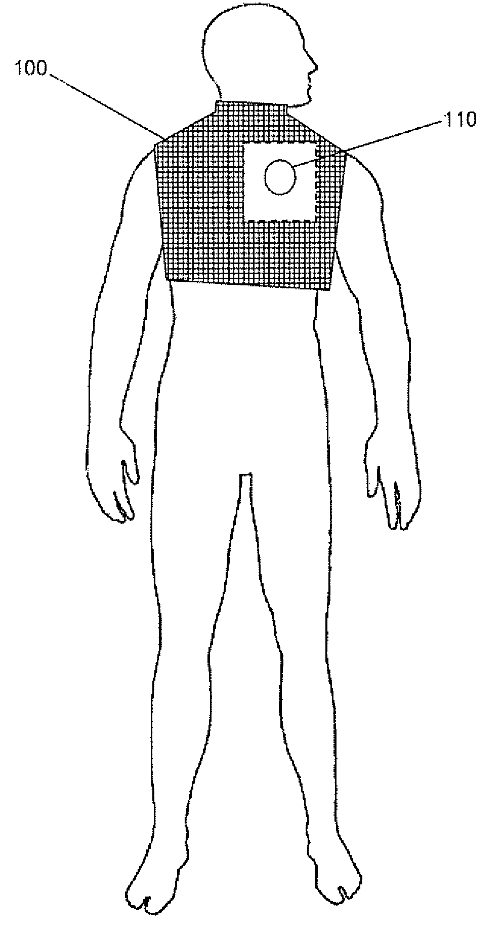
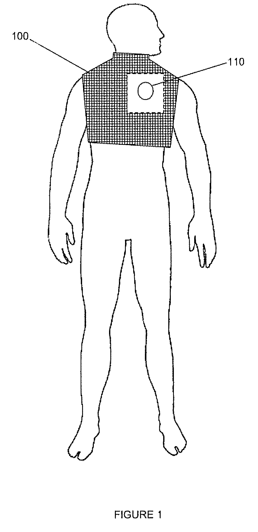
[0022]FIG. 1 illustra...


PUM


Abstract

Methods and apparatus for reducing the heating of an implantable medical device due to RF energy. An RF shield is disclosed which provides localized RF shielding of an implantable medical device while allowing other portions of a patient's body to be exposed. The RF shield described is made from an RF energy absorbing fabric which circumferentially wraps around a portion of a patient's body. The RF energy absorbing fabric can be composed of carbon fibers, conductive metal fibers, or combinations thereof. An advantage of the disclosed RF shield is that it need not be implanted within a patient.

Description

CROSS-REFERENCE TO RELATED APPLICATIONS[0001]Not applicable.BACKGROUND[0002]1. Technical Field[0003]The subject matter of this disclosure generally relates to the field of implantable medical devices. More specifically, the present disclosure relates to reducing heat generated in an implantable medical device during imaging such as magnetic resonance imaging.[0004]2. Background Information[0005]Magnetic resonance (MR) imaging (MRI) uses radiofrequency (RF) waves and a strong magnetic field rather than x-rays to provide remarkably clear and detailed pictures of internal organs and tissues. The technique has proven very valuable for the diagnosis of a broad range of pathologic conditions in all parts of the body including cancer, heart and vascular disease, stroke, and joint and musculoskeletal disorders. MRI requires specialized equipment and expertise and allows evaluation of some body structures that may not be visible in similar detail with other imaging methods.[0006]Certain impl...

Claims


Application Information

Patent Timeline
Patent Type & Authority Applications(United States)
IPC IPC(8): A61F5/37
CPCA61N1/08G01R33/422A61N1/3718
Inventor INMAN, D. MICHAELMASCHINO, STEVEN E.
Owner LIVANOVA USA INC
Why Eureka
Try Eureka