Piezoelectric actuator and scanning probe microscope using the same

a scanning probe microscope and actuator technology, applied in the field of piezoelectric actuators, can solve the problems of inability to achieve the effect of bringing about a drawback of a material, the prepressure applied on the piezoelectric element is increased, and the piezoelectric element is overheated to be destructed, etc., to achieve a high speed, stably be measured, and the effect of op

Inactive Publication Date: 2008-01-31
HITACHI HIGH TECH SCI CORP
View PDF1 Cites 5 Cited by
  • Summary
  • Abstract
  • Description
  • Claims
  • Application Information

AI Technical Summary

Benefits of technology

[0014] According to the piezoelectric actuator according to the invention, the following effect is achieved.
[0015] The elastic member constituting the prepressurizing structure is provided with a high resonance frequency, and therefore, even when the piezoelectric actuator is driven to vibrate at high speed, it is difficult to jump up the elastic member. Further, since the spring constant of the prepressurizing structure is small, and excessively large prepressurizing load is not applied to the piezoelectric element, the displacement of the piezoelectric element can stably be measured, and the piezoelectric actuator can stably be operated at high speed.
[0016] Further, when the elastic member having the above-described shape is used as the prepressurizing structure, a strain produced at the elastic member when the piezoelectric element is displaced is concentrated on the periphery of the end portion on a side of the piezoelectric element, and therefore, by attaching the strain gage sensor to the portion, the displacement of the piezoelectric element can be detected as the large signal, and a detection accuracy can be promoted.
[0017] According to the scanning probe microscope according to the invention, the above-described piezoelectric actuator is used as the moving means, and therefore, a stable measurement can be carried out, and also the detection accuracy can be promoted.

Problems solved by technology

However, in a case of driving the piezoelectric actuator at high speed, when a resonance frequency of the spring constituting the prepressurizing structure is low, there is case of jumping up the spring by the piezoelectric element.
However, according to the former method, there is a possibility that a prepressure applied on the piezoelectric element is increased by increasing the spring constant and the piezoelectric element cannot be displaced in a case of a small-sized piezoelectric element having a small generating power used for a use of being driven at high speed.
In this case, an energy for displacing is changed into a heat amount, and therefore, there is a concern that the piezoelectric element is overheated to be destructed.
Further, according to the method of using the light material, generally, a material having a small density is provided with a low Young's modulus, and therefore, an effect cannot be achieved to bring about a drawback that a material is limited.

Method used


Image

  • Piezoelectric actuator and scanning probe microscope using the same
  • Piezoelectric actuator and scanning probe microscope using the same
  • Piezoelectric actuator and scanning probe microscope using the same

Examples


first embodiment

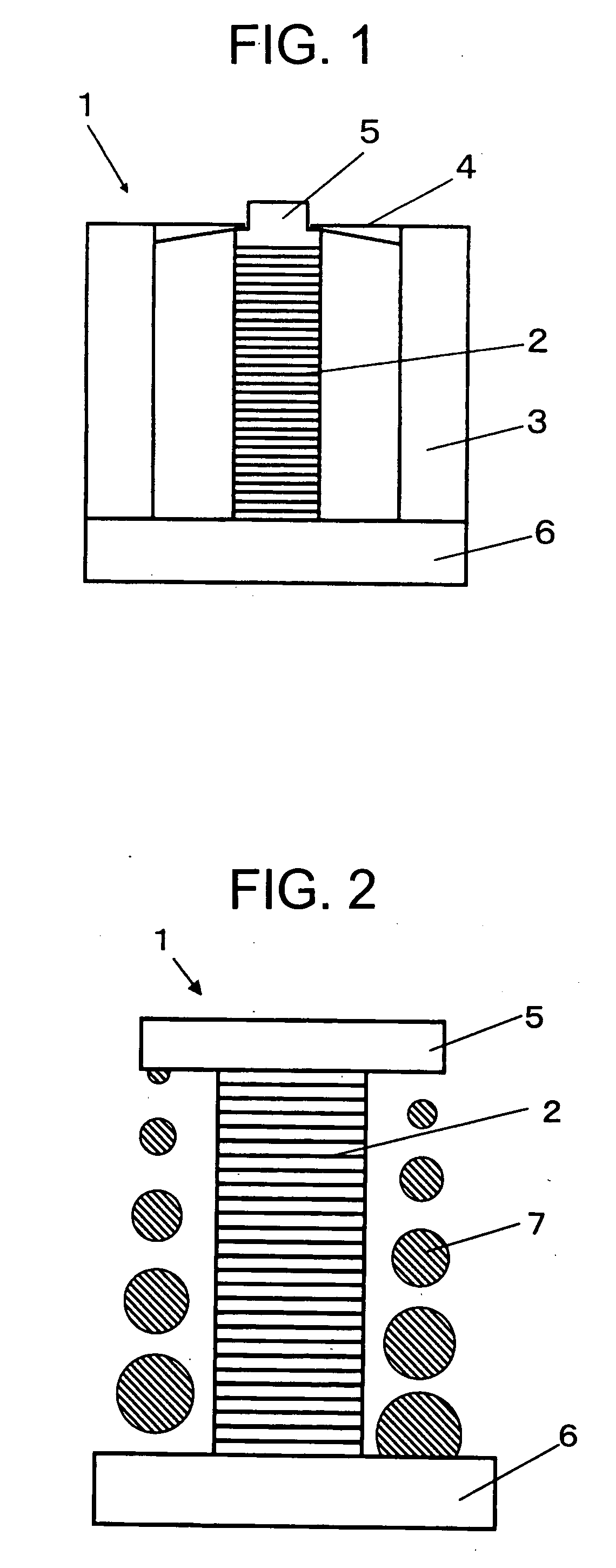
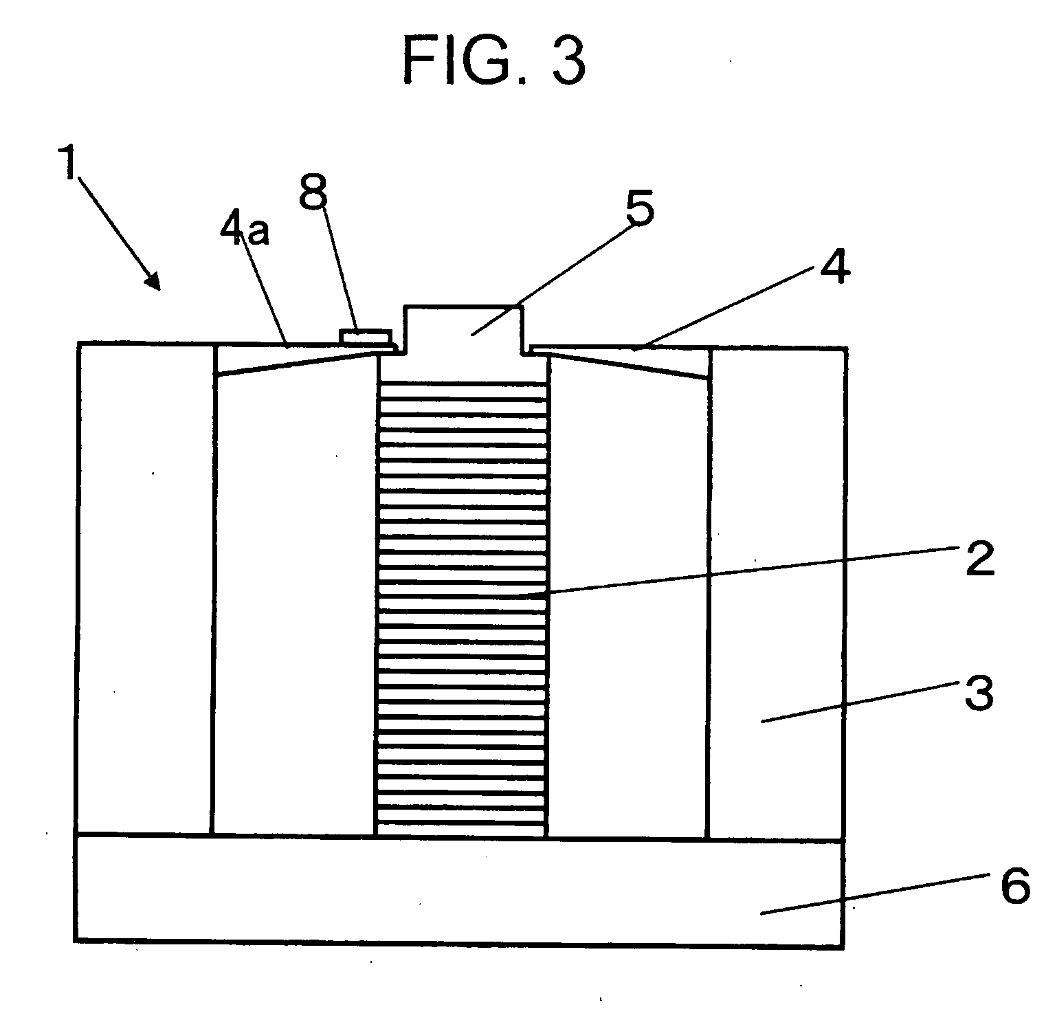
[0022] a piezoelectric actuator according to the invention will be explained in reference to an outline constitution view of FIG. 1 as follows.

[0023] That is, a piezoelectric actuator 1 according to the first embodiment comprises a laminating type piezoelectric element 2 constituting a piezoelectric element displaced by applying a voltage, a foundation 6 for fixing one end of the laminating type piezoelectric element 2, a driven member 5 fixed to other end of the laminating type piezoelectric element 2, and a leaf spring 4 constituting an elastic member one end of which is indirectly fixed to the foundation 6, other end of which is brought into contact with the laminating type piezoelectric element 2 and which prepressurizes the laminating type piezoelectric element 2 in a compressing direction, and is characterized in that the leaf spring 4 is constituted by a shape by which a moment of inertia of a portion thereof on other end brought into contact with the laminating type piezoele...

second embodiment

[0031] That is, the piezoelectric actuator 1 of the second embodiment is constituted by the laminating type piezoelectric element 2 constituting the piezoelectric element displaced by applying a voltage, the foundation 6 for fixing one end of the laminating type piezoelectric element 2, the driven member 5 fixed to other end of the laminating type piezoelectric element 2, and a coil spring 7 constituting an elastic member one end of which is directly fixed to the foundation 6, other end of which is brought into contact with the driven member 5 and which prepressurizes the laminating type piezoelectric element 2 in a compressing direction, the coil spring 7 is characterized in being constituted by a shape in which a moment of inertia on a side of a portion of other end brought into contact with the driven member 5 is smaller than that of a portion of one end side fixed to the foundation 6.

[0032] Here, according to the embodiment, as the elastic member, there is used an elastic member...

third embodiment

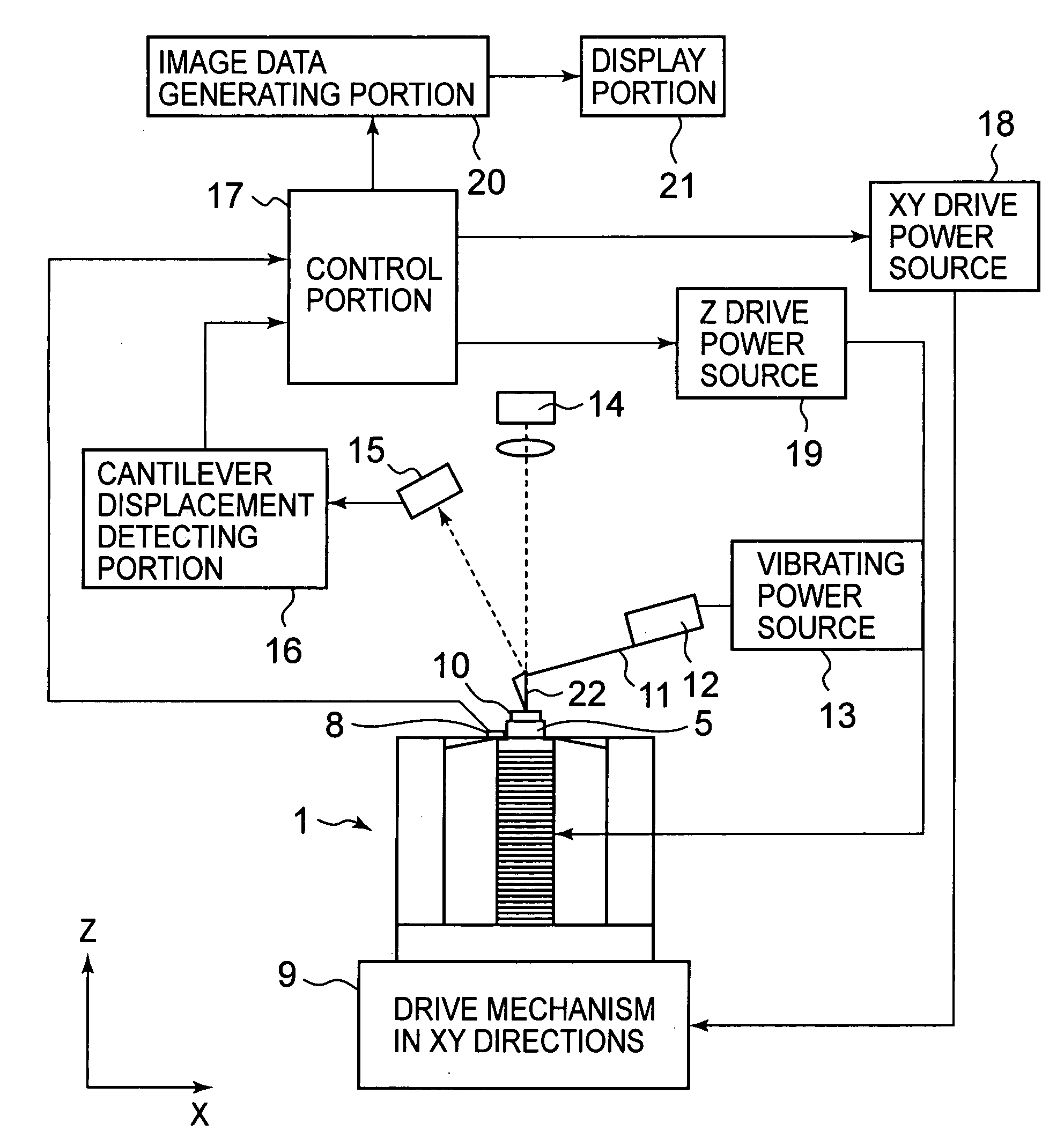
[0042] Further, according to the scanning probe microscope of the embodiment, as shown by FIG. 4, the sample 10 is arranged above the stage, not illustrated, mounted above the driven member 5 of the piezoelectric actuator explained in the That is, according to the scanning probe microscope of the embodiment, the sample 10 is moved in Z direction constituting a longitudinal direction of a paper face. Further, according to the scanning probe microscope of the embodiment, the sample 10 is moved in XY directions constituting two directions orthogonal to the paper face by a driving mechanism 9 in XY directions. Therefore, a position of the sample 10 can be moved three-dimensionally in XYZ directions by the moving mechanism and a position thereof relative to the probe 22 can be changed.

[0043] Further, the piezoelectric actuator 1 similar to that described in the third embodiment is used, and therefore, the same notations are attached and an explanation thereof will be omitted. Further, t...


PUM


Abstract

A leaf spring 4 constituting an elastic member one end of which is fixed to a foundation 6, and other end of which is brought into contact with a laminating type piezoelectric element 2 or a driven member 5 is constituted such that a thickness is thinned from a side of the foundation 6 to a side of the laminating type piezoelectric element 2 to make a moment of inertia smaller on a side of a portion of other end held by the laminating type piezoelectric element 2 than a portion on one end side fixed to the foundation 6. Further, a strain gage sensor 8 is attached to a side face 4a of the leaf spring 4 constituting one face of one end of the leaf spring 4 proximate to the laminating type piezoelectric element 2 orthogonal to a direction of elongating and contracting the laminating type piezoelectric element 2 constituting a side of the driven member 5.

Description

BACKGROUND OF THE INVENTION [0001] The present invention relates to a piezoelectric actuator utilizing a piezoelectric effect and a scanning probe microscope using the same. [0002] In a piezoelectric actuator using a piezoelectric element displaced by applying a voltage, there is known a structure of a laminating type piezoelectric element laminated with a plurality of piezoelectric elements for pressurizing a piezoelectric actuator by using a prepressurizing structure generally using a spring previously in order to prevent an exfoliation among layers of the respective piezoelectric elements or a distortion of a displacement by clearances among the layers to ensure a stable operation (refer to, for example, Patent Reference 1). [0003] However, in a case of driving the piezoelectric actuator at high speed, when a resonance frequency of the spring constituting the prepressurizing structure is low, there is case of jumping up the spring by the piezoelectric element. In this case, the p...

Claims


Application Information

Patent Timeline
Patent Type & Authority Applications(United States)
IPC IPC(8): H01J3/14H02N2/04G01Q10/04
CPCB82Y35/00H01L41/083H01L41/053G01Q10/04H10N30/886H10N30/50
Inventor WATANABE, MASAFUMI
Owner HITACHI HIGH TECH SCI CORP
Why Eureka
Try Eureka