Cylindrical vibration-damping device and method of producing the same, and vibration-damping structure including the cylindrical vibration-damping device

a cylindrical, vibration-damping technology, applied in the direction of machine supports, hollow wall objects, shock absorbers, etc., can solve the problems of limited damping effect, limited frequency range of conventional devices, and large installation space of damping materials, etc., to achieve easy installation, expand installation style, and high accuracy

Inactive Publication Date: 2008-01-31
SUMITOMO RIKO CO LTD
View PDF1 Cites 25 Cited by
  • Summary
  • Abstract
  • Description
  • Claims
  • Application Information

AI Technical Summary

Benefits of technology

[0036]Accordingly, the processes of fitting the vibration-damping device externally from the axial end of the vibrating member and moving the vibration-damping device to the intended position are omitted, making it easy to install the vibration-damping device on the vibrating member. In addition, it is also possible to mount the vibration-damping device on the vibrating member whose end is already secured to another member and is closed off, thereby advantageously expanding installation style. In addition, there is no special need to take into consideration features including a shape or size of an area of the vibrating member other than the position where the vibration-damping device ...

Problems solved by technology

A variety of rod shaped vibrating members including power transmitting members such as shafts, arms and beams as well as pipes forming fluid passages are likely to cause problems of resonance themselves and vibration transmission therethrough.
However, these conventional devices suffer from various potential problems.
For instance, the mass damper and the dynamic damper require a relatively large mass of the pillar-shaped mass member, and exhibit damping effects limited to a considerably narrow frequency range.
The damping material requires a relatively large space for its installation, and tends to be large in its weight.
In addition, the dynamic damper suffers from difficulty in stably exhibiting desired damping effects thereof, since the damping effects of rubber material which constitutes a spring member of a mass-spring system of the dynamic damper is prone to vary depending upon the ambient temperature.
However, the proposed vibration damper also suffers from problems in tuning in order to exhibit an excellent damping effect with respect to a desired frequency vibration.
That is, tuning of the vibration damper is limited by several conditions.
For instance, modifying a size of the independent mass member is limited by a given space for installation in the housing, while adjusting the spring rigidity of the elastic material which constitutes the elastic abutting surface of the independent mass member against the h...

Method used


Image

  • Cylindrical vibration-damping device and method of producing the same, and vibration-damping structure including the cylindrical vibration-damping device
  • Cylindrical vibration-damping device and method of producing the same, and vibration-damping structure including the cylindrical vibration-damping device
  • Cylindrical vibration-damping device and method of producing the same, and vibration-damping structure including the cylindrical vibration-damping device

Examples


first embodiment

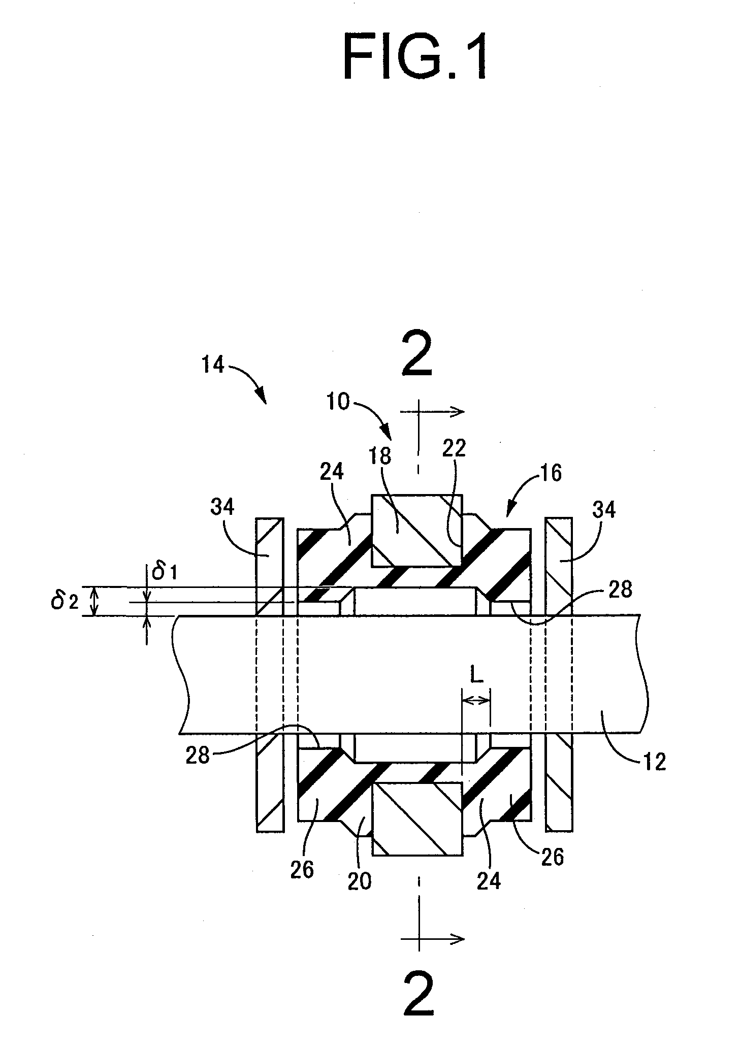
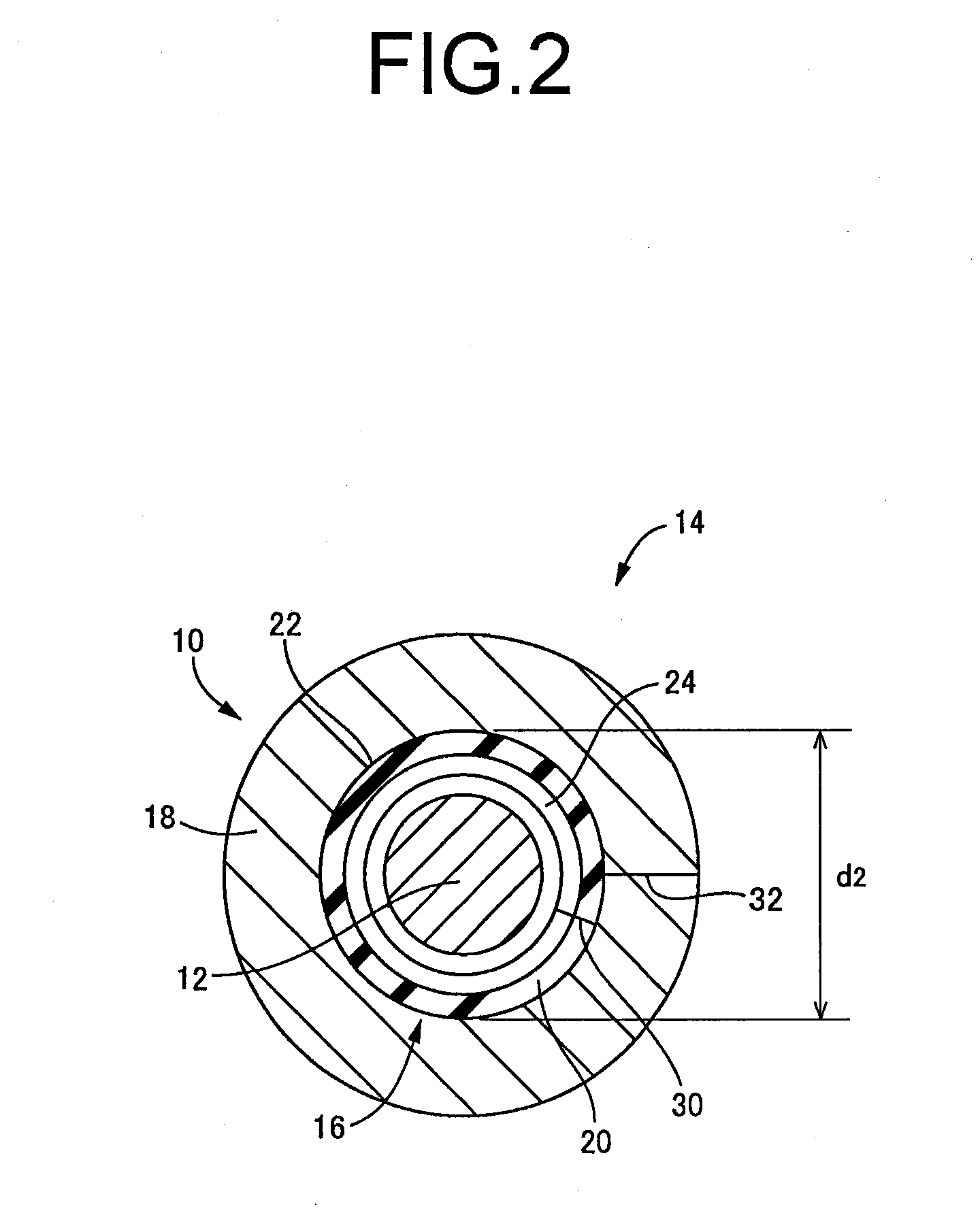
[0051]Referring first to FIGS. 1 and 2, shown is a vibration-damping structure 14 including a cylindrical vibration-damping device 10 constructed according to the invention which is mounted around an arm 12 serving as a rod shaped vibrating member. The vibration-damping device 10 including a main rubber elastic body 16 and a mass member 18 is mounted around the arm 12, namely, a primary vibration system, so as to constitute a secondary vibration system with respect to the primary vibration system.

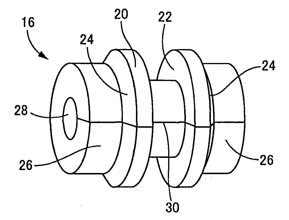
[0052]Described in detail, as shown in FIG. 3, the main rubber elastic body 16 is of generally cylindrical shape and formed of a rubber elastic material. The rubber elastic material may preferably have a Shore D hardness of 80 or lower, more preferably, within a range of 20-40, as measured in accordance with ASTM method D-2240, and may be preferably selected from a simple substance of natural rubber, styrene-butadiene rubber, isoprene rubber, acrylonitrile-butadiene rubber, chloroprene rubb...

third embodiment

[0111]FIG. 8 shows a vibration-damping structure 71 including a cylindrical vibration-damping device 70 constructed according to the invention which is mounted around the arm 12. Specifically, as shown in FIG. 8 for example, the main rubber elastic body 16 may be provided with a plurality of the mass installation grooves 22 (in this embodiment, three) positioned axially apart from one another and each having the mass member 18 fixed thereto. With this arrangement, the abutting inner surfaces 28 are formed between areas where the mass installation grooves 22, 22 which are axially adjacent to each other are formed. In addition, the abutting inner surfaces 28 are further formed axially outward from the mass installation grooves 22 positioned near the axially opposite ends of the main rubber elastic body 16. That is, the abutting inner surface 28 is formed on axially either side of the each mass installation groove 22.

[0112]Besides, as shown in FIG. 8, the shape, dimension or other aspe...

fourth embodiment

[0113]FIG. 9 shows a vibration-damping structure 81 including a cylindrical vibration-damping device 80 constructed according to the invention which is mounted around the arm 12. As shown in FIG. 9, it could also be possible that a main rubber elastic body 48 of cylindrical shape includes: the tapered portion 24 at its axially central portion; a large-diameter cylindrical portion 50 on axially one side of the tapered portion 24; a small-diameter cylindrical portion 52 having a smaller diameter than that of the large-diameter cylindrical portion 50 on axially the other side of the tapered portion 24; and the mass installation groove 22 opening in an outer circumferential surface of the large-diameter cylindrical portion 50 and having the mass member 18 fixed thereto. In the vibration-damping device 80, an inner circumferential surface of the small-diameter cylindrical portion 52 forms the abutting inner surface 28 of the main rubber elastic body 48 adapted to come into abutting conta...


PUM

PropertyMeasurementUnit
Lengthaaaaaaaaaa
Massaaaaaaaaaa
Diameteraaaaaaaaaa

Abstract

Disclosed is a method of producing an impact-type cylindrical vibration-damping device comprising the steps of: preparing a main rubber elastic body of hollow cylindrical shape including a mass installation groove open in an outer circumferential surface thereof and a slit extending over an entire axial length thereof; expanding the elastic body at the slit in order to mount the elastic body about a rod shaped vibrating member through the slit from a radially outer side such that the elastic body has an abutting inner surface adapted to come into abutting contact against the vibrating member at a portion where a radial distance between an inner circumferential surface of the elastic body and an outer circumferential surface of the vibrating member is smallest; preparing a mass member separately from the elastic body; and fixing the mass member to the elastic body by fitting the mass member onto the mass installation groove.

Description

INCORPORATED BY REFERENCE[0001]The disclosure of Japanese Patent Application No. 2006-206403 filed on Jul. 28, 2006 including the specification, drawings and abstract is incorporated herein by reference in its entirety.BACKGROUND OF THE INVENTION[0002]1. Field of the Invention[0003]The present invention relates to a cylindrical vibration-damping device adapted to be mounted on hollow or solid rod shaped vibrating members such as a variety of shafts, arms and pipes, and capable of exhibiting vibration damping action against vibrations excited in the vibrating members due to vibration transmitted therethrough. The present invention also relates to a method of producing the above-described vibration-damping device; and a vibration-damping structure including the cylindrical vibration-damping device.[0004]2. Description of the Related Art[0005]A variety of rod shaped vibrating members including power transmitting members such as shafts, arms and beams as well as pipes forming fluid pass...

Claims


Application Information

Patent Timeline
IPC IPC(8): F16F15/08
CPCF16F7/108
Inventor HASEGAWA, KOICHIMURAMATSU, ATSUSHI
Owner SUMITOMO RIKO CO LTD
Why Eureka
Try Eureka