Low-gain current-mode voltage regulator

Active Publication Date: 2008-01-31
RICHTEK TECH +1
View PDF1 Cites 29 Cited by
  • Summary
  • Abstract
  • Description
  • Claims
  • Application Information

AI Technical Summary

Benefits of technology

[0005]An object of the present invention is directed to precisely control the droop of a low-gain current-mode voltage regulator.
[0006]Specifically, an object of the present invention is directed to cancel the output offset of a low-gain current-mode voltage regulator.
[0007]Accordingly, an object of the present invention is directed to precisely control the output voltage of a low-gain current-mode voltage regulator.
[0008]In a low-gain current-mode voltage regulator, according to the present invention, an offset cancellation circuit is provided to add an offset to a PWM comparator to cancel the output offset of

Problems solved by technology

However, increasing the size of the output capacitor will increase the volume, weight and cost of the voltage regulator.
It is therefore a stringent challenge on the voltage regulator module (VRM) for real applications.
Unfortunately, in a low-gain curr

Method used


Image

  • Low-gain current-mode voltage regulator
  • Low-gain current-mode voltage regulator
  • Low-gain current-mode voltage regulator

Examples


Example

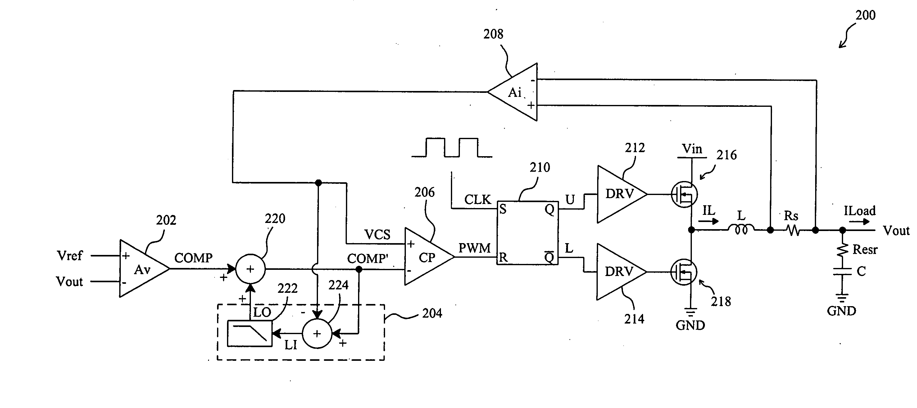
[0019]FIG. 5 shows an embodiment of the present invention, and FIG. 6 is a waveform diagram to show various signals thereof. In a low-gain current-mode voltage regulator 200, a high-side switching signal U and a low-side switching signal L switch a high-side transistor 216 and a low-side transistor 218 serially connected between an input voltage Vin and ground GND with two drivers 212 and 214, respectively, to produce an inductor current IL to charge an output capacitor C to produce an output voltage Vout, an error amplifier 202 has a gain Av to amplify the difference between the output voltage Vout and a reference voltage Vref to produce an error signal COMP, a voltage amplifier 208 has a gain Ai to amplify the voltage drop across a current sense resistor Rs serially connected to the inductor L to produce a current sense signal VCS, a combiner 220 combines the error signal COMP and an offset signal LO provided by an offset cancellation circuit 204 to produce a modified error signal...


PUM


Abstract

In a low-gain current-mode voltage regulator having a PWM comparator in response to the varying output voltage and inductor current of the voltage regulator to produce a PWM signal to regulate the output voltage, an offset signal is derived from a subtraction between the inputs of the PWM comparator, and the offset signal is injected into the PWM comparator to cancel the output offset of the voltage regulator.

Description

FIELD OF THE INVENTION[0001]The present invention is related generally to a voltage regulator and, more particularly, to a low-gain current-mode voltage regulator.BACKGROUND OF THE INVENTION[0002]Voltage regulators have been widely used in various electronic devices to implement the power supplies for providing stable supply voltages for the circuits in the electronic devices. However, spike will be generated on the output voltage of the voltage regulator in load transient resulted from instant load change, and large voltage spike may damage the load connected to the voltage regulator. FIG. 1 is a waveform diagram to show the output signals of a conventional voltage regulator in a load transient, in which waveform 100 represents the load current ILoad and waveform 102 represents the output voltage Vout. At time t1, in response to the load changing from light to heavy, the load current ILoad steps up, and the output voltage Vout drops down from the nominal voltage by a difference ΔV ...

Claims


Application Information

Patent Timeline
IPC IPC(8): G05F1/00
CPCH02M3/158
Inventor HUANG, JIAN-RONGTSENG, KUO-LUNGBERNACCHIA, GIUSEPPEINVERSI, MAURIZIO
Owner RICHTEK TECH
Why Eureka
Try Eureka