

High-Frequency Coupler, Rf Guide, and Antenna
a high-frequency coupler and guide technology, applied in the direction of coupling devices, transformers/inductance coils/windings/connections, electrical apparatus, etc., can solve the problem that the electrical coupling between the balanced line and the unbalanced line cannot be produced insufficient degree, and achieve the effect of better transmission characteristics
- Summary
- Abstract
- Description
- Claims
- Application Information
AI Technical Summary
Benefits of technology
Problems solved by technology
Method used
Image

Examples
Embodiment Construction
[0043] The present invention shall be described below with reference to the drawings.
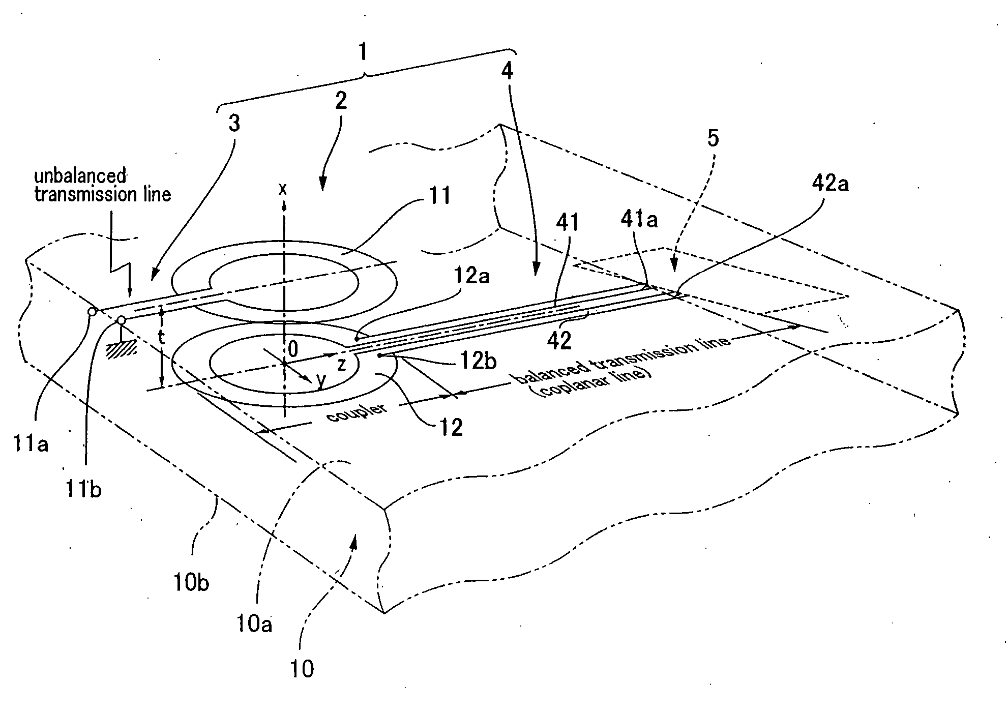
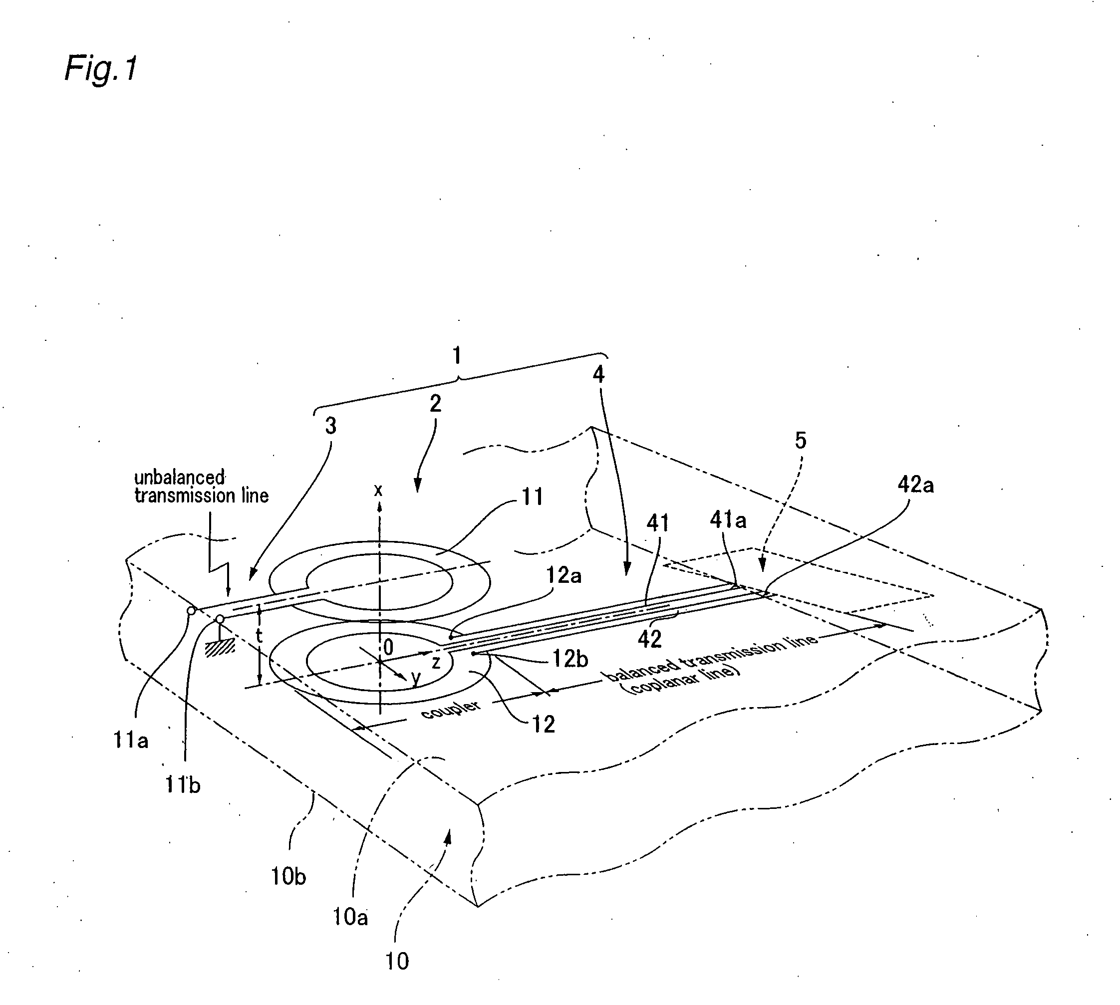
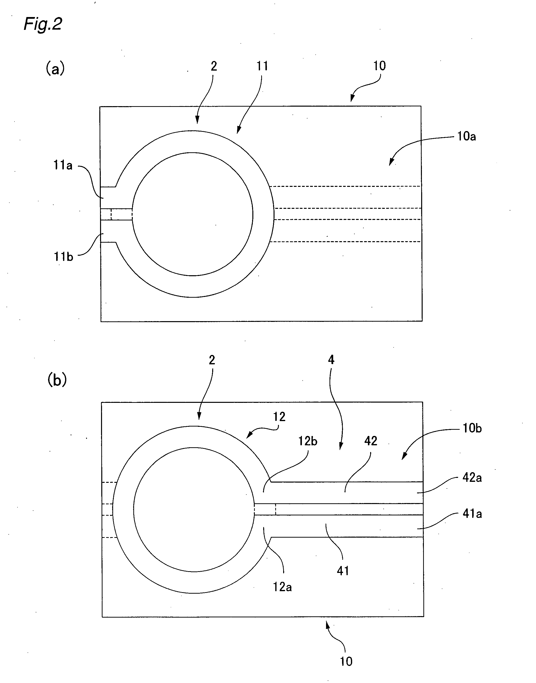
[0044]FIG. 1 is a descriptive view showing an RF guide that uses the present invention. FIGS. 2(a) and 2(b) are a rear view and plan view of the RF guide. An RF guide 1 of the present example has a high-frequency coupler 2 and an unbalanced transmission line 3 and balanced transmission line 4 that are mutually coupled via the high-frequency coupler 2.
[0045] The high-frequency coupler 2 has a circuit board 10 composed of a dielectric body. A loop-shaped first coupler pattern 11 that is broken in one location is formed from copper foil or the like on a rear surface (first board surface) 10a of the circuit board 10. A loop-shaped second coupler pattern 12 that is broken in one location is similarly formed from copper foil or the like on a front surface (second board surface) 10b. The first and second coupler patterns 11, 12 have, e.g., identical annular shapes.
[0046] The positions at which the first...
PUM
 Abstract
Description
Claims
Application Information