Magnetic disk device

a magnetic disk and disk assembly technology, applied in the direction of electrical apparatus construction details, instruments, record information storage, etc., can solve the problems of difficult estimation, certain air turbulence, and vibration in the disk and head gimbal assembly, and achieve the effect of improving bonding reliability

Active Publication Date: 2008-01-31
WESTERN DIGITAL TECH INC
View PDF9 Cites 18 Cited by
  • Summary
  • Abstract
  • Description
  • Claims
  • Application Information

AI Technical Summary

Benefits of technology

[0008] Embodiments in accordance with the present invention provide improve bonding reliability in a feedthrough sealing portion. According to the particular embodiments of FIGS. 1 and 3A, an opening 7 of a through hole is provided on the bottom of the base 2 of the magnetic disk device 20, and a feedthrough mounting plane 8 which is one of the steps formed toward the outside of the device, is provided around the opening 7. The feedthrough 1 includes a flange 4 and pins 3 which are fixed to the flange 4 by a glass material 5 and pass an electric signal. The flange 4 is larger in outer shape than the opening 7 of the base 2. The periphery of the flange 4 of the feedthrough 1 is mounted on the feedthrough mounting plane 8 of the base 2 from the outside and bonded thereto by solder.

Problems solved by technology

To meet these demands, a disk and a head gimbal assembly are rotated and driven at a high speed respectively, which creates a certain amount of air turbulence, thereby producing vibration in the disk and head gimbal assembly.
The reason is that air turbulence is randomly created, which makes it difficult to estimate its size and period, making it complicated and difficult to control a quick and accurate positioning.
In addition, the turbulence vibration produces noise, which leads to a loss of the quietness of the device.
Aside from the above, the air turbulence created by a high speed rotation in the device causes a problem with increase in consumption power.
However, there has been a problem in that helium readily leaks out during use from a housing used in an ordinary magnetic disk device inferior in hermetic because helium is very small in molecule and large in diffusion coefficient.
However, solder used for bonding the feedthrough to the base is low in proof stress as material, so that it may not ensure sufficient bonding reliability depending on external force applied to a magnetic disk device or unexpected deformation caused by change in temperature environment while the magnetic disk device is used.

Method used


Image

  • Magnetic disk device
  • Magnetic disk device
  • Magnetic disk device

Examples


second embodiment

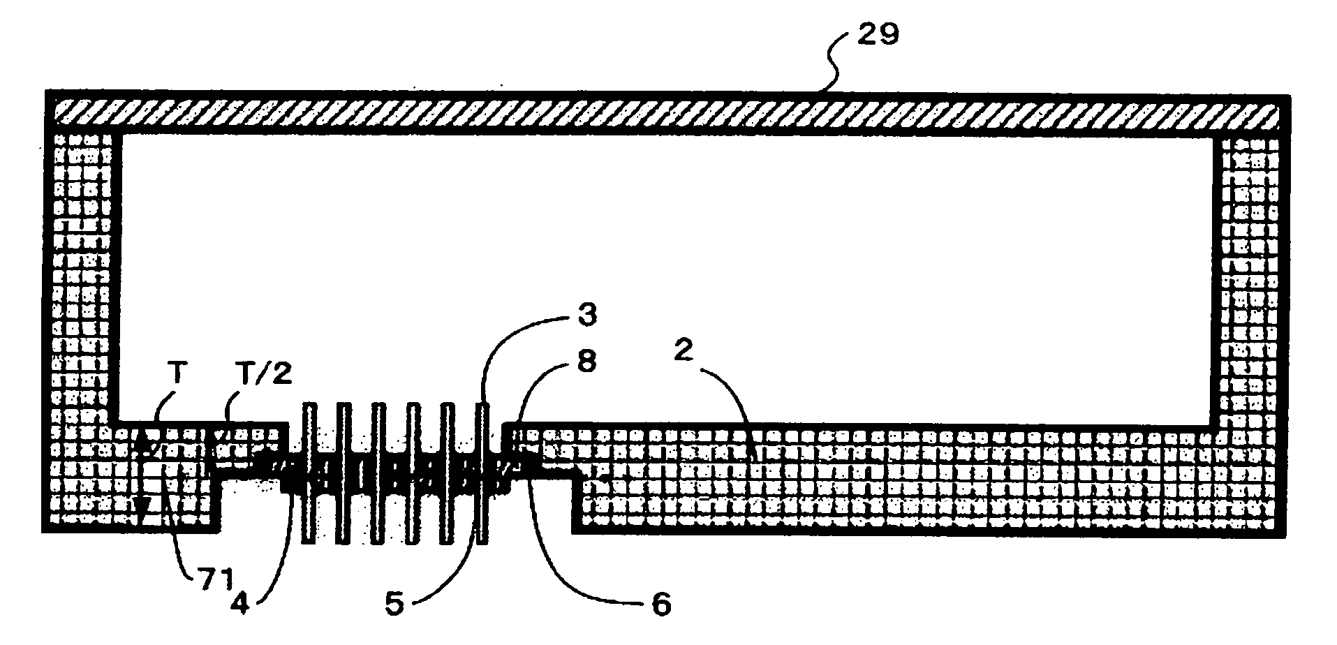
[0051]FIG. 4 shows a cross section of a portion where the feedthrough of the magnetic disk device according to the present invention is mounted. Also in the figure, the HDA shown in FIG. 3B is omitted and the periphery of the feedthrough is enlarged. Incidentally, the feedthrough 1 is substantially the same in total configuration as that shown in FIG. 1.

[0052] As shown in FIG. 4, a step as the feedthrough mounting plane 8 is provided in a position closer to the inside of the device than the center 71 of thickness of the base 2, in other words, if the thickness of the base is taken to be T, the feedthrough mounting plane 8 is situated in the position closer to the inside of the device than the position of T / 2.

[0053] According to the present structure, the feedthrough mounting plane 8 is provided in the position closer to the inside of the device than the center 71 of the thickness of the base 2, which enables changing the direction to which the base 2 is deformed to suppress deforma...

third embodiment

[0060]FIG. 5 shows a perspective view of a feedthrough according to the

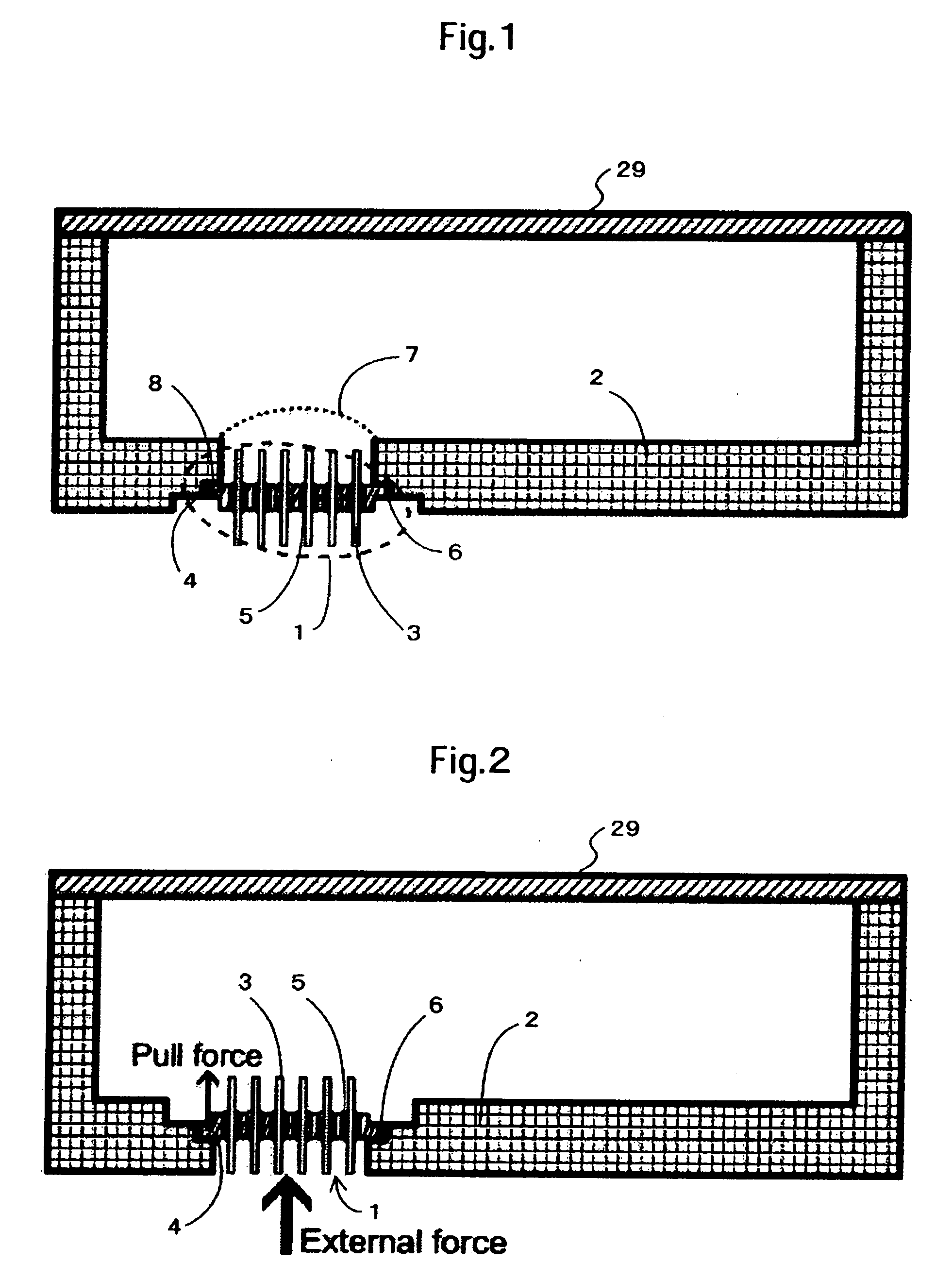
[0061] In the above second embodiment, the deformation of the base 2 offsets that of the feedthrough 2 to suppress the out-of-plane deformation of the flange 4, however, this does not always mean that the out-of-plane deformation thereof is completely suppressed.

[0062] For this reason, as shown in FIG. 5, a ditch 9 is provided in the plane that is the periphery of the flange 4 inside the device.

[0063] According to the present structure, the deformation of the feedthrough can be restricted to the periphery of the ditch and precluded from extending to the whole area. As a result, stress applied to the solder bonding portion 6 can be further suppressed.

[0064]FIGS. 8A and 8B show the states that the feedthrough 1 and the solder bonding portion 6 are deformed due to a change in temperature. FIG. 8A shows results obtained by the finite element method by calculating deformation for cases where temperature is changed ...


PUM

PropertyMeasurementUnit
stressaaaaaaaaaa
radiusaaaaaaaaaa
densityaaaaaaaaaa

Abstract

Embodiments in accordance with the present invention improve bonding reliability in a feedthrough sealing portion. According to one embodiment of the present invention, an opening of a through hole is provided on the bottom of the base of the magnetic disk device and a feedthrough mounting plane which is one of the steps formed toward the outside of the device is provided around the opening. The feedthrough includes a flange and pins which are fixed to the flange by a glass material and pass an electric signal. The flange is larger in outer shape than the opening of the base. The periphery of the flange of the feedthrough is mounted on the feedthrough mounting plane of the base from the outside and bonded thereto by solder.

Description

[0001] The instant nonprovisional patent application claims priority to Japanese Patent Application No. 2006-158277 filed Jun. 7, 2006 and incorporated by reference in its entirety herein for all purposes BACKGROUND OF THE INVENTION [0002] Recently, there have been demands for a magnetic disk device to have large capacity, high recording density and high access. To meet these demands, a disk and a head gimbal assembly are rotated and driven at a high speed respectively, which creates a certain amount of air turbulence, thereby producing vibration in the disk and head gimbal assembly. The turbulence vibration hinders a head from being positioned on a high-density recorded disk data. The reason is that air turbulence is randomly created, which makes it difficult to estimate its size and period, making it complicated and difficult to control a quick and accurate positioning. In addition, the turbulence vibration produces noise, which leads to a loss of the quietness of the device. [000...

Claims


Application Information

Patent Timeline
Patent Type & Authority Applications(United States)
IPC IPC(8): G11B33/14
CPCG11B25/043G11B33/1466G11B33/122G11B33/14
Inventor NAKAMIYA, TERUHIROSHINDO, HITOSHIHAYAKAWA, TAKAKOUEFUNE, KOUKI
Owner WESTERN DIGITAL TECH INC
Why Eureka
Try Eureka