Communication system for hazardous environments

a communication system and hazardous environment technology, applied in the field of communication systems, can solve the problems of ethernet system not producing sparks, hazardous areas, and potential ignition of atmosphere, and achieve the effect of reducing the potential energy level of signals under normal and fault conditions, and facilitating the assessment of intrinsic safety

Inactive Publication Date: 2008-01-31
CONTROLLED SYST
View PDF7 Cites 8 Cited by
  • Summary
  • Abstract
  • Description
  • Claims
  • Application Information

AI Technical Summary

Benefits of technology

[0011]An advantage of the present invention is that, by limiting the energy of the data signals transmitted to below a pre-determined (i.e. Intrinsically Safe) level, the system can still be operated under live-working conditions, since the energy of the data signals is insufficient to produce a spark. Further, the capacitors block the higher power DC component but allow the small high frequency component of the data signal to pass because they offer only a low impedance path to the data signal. Thus, the potential energy level of the signal under normal and fault conditions is greatly reduced because the DC component is removed, but the small data signal carried by the high frequency component of the signal is unaffected. This makes for an easier assessment against Intrinsic Safety.
[0012]Generally the energy limiting means will comprise at least two capacitors.
[0013]Preferably the devi

Problems solved by technology

Areas are considered hazardous where there is an atmosphere containing flammable or combustible materials (e.g. fuels, flammable gases, explosive vapours, combustible dusts, etc), and where the atmosphere has the potential to ignite.
This means that the Ethernet system must not produce a spark that has sufficient energy or heat to cause an ignition of gases or dusts both during normal operation and when in a fault condition.
However, there are problems in rendering an Ethernet system non-incendive or Intrinsically Safe because there is a conflict between the performance requirements of the Ethernet system and the energy-limitation required to render it non-incendive or Intrinsically Safe.
So far, Ethernet systems have found limited applications in the least onerous hazardous are

Method used


Image

  • Communication system for hazardous environments
  • Communication system for hazardous environments
  • Communication system for hazardous environments

Examples


Embodiment Construction

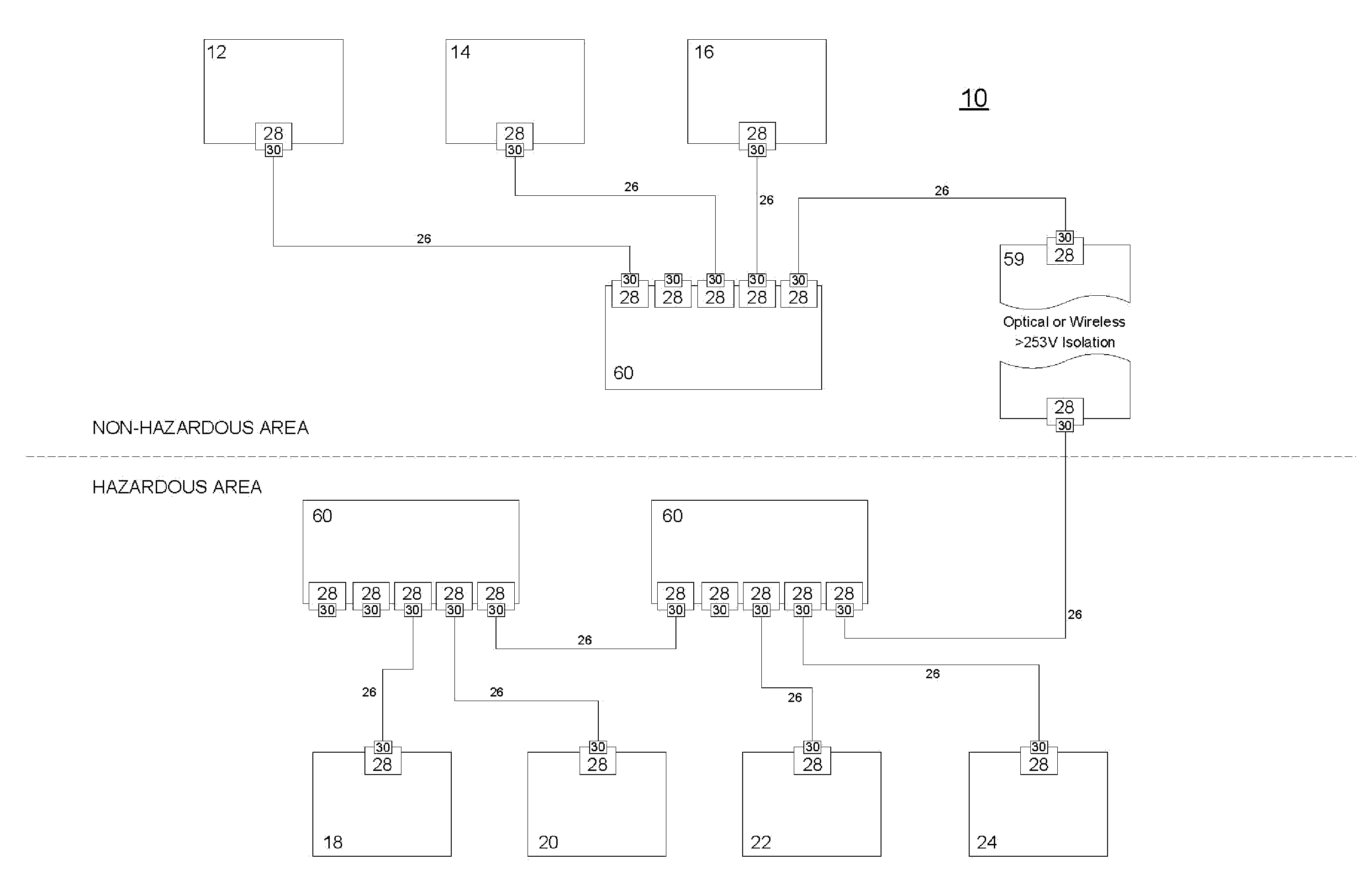
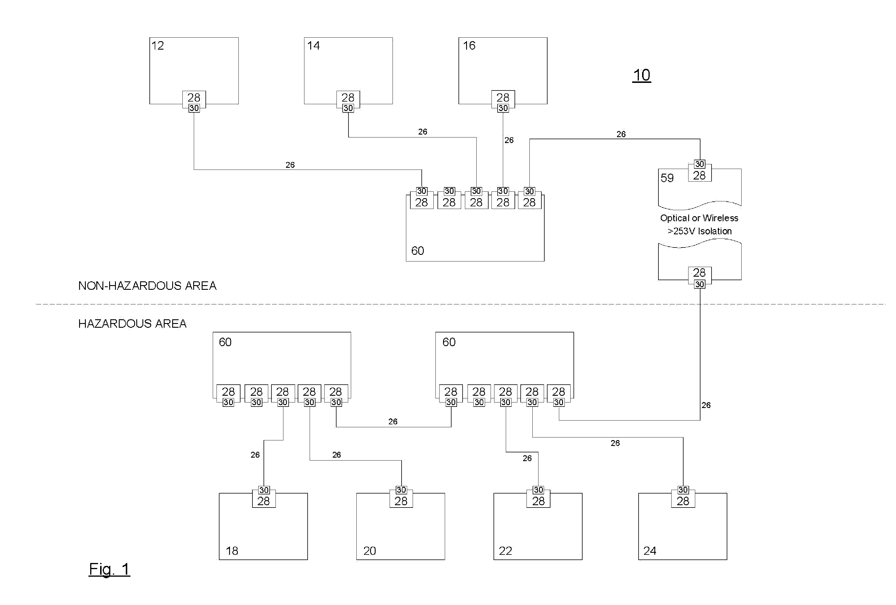
[0036]As mentioned, FIG. 1 illustrates a communication system 10 which includes a plurality of (Non-Intrinsically Safe) devices 12, 14, 16 (for example, a personal computer, server, HMI Interface, etc.) and a plurality of Intrinsically Safe (I.S.) apparatus 18, 20, 22, 24 (for example, Remote I / O, Process Controller, etc.). Each of the plurality of devices 12, 14, 16 and the plurality of I.S. apparatus 18, 20, 22, 24 are communicatively coupled to each other by way of communication buses 26. The apparatus and devices are typically interconnected at a switching hub 60, which manages crossing over of transmit and receive pairs as required. In the present embodiment, the function of the plurality of devices 12, 14, 16 and the plurality If I.S. apparatus 18, 20, 22, 24 is unimportant. However, for illustrative purposes, the plurality of I.S. apparatus 18, 20, 22, 24 may perform detection, actuation, etc. and the plurality of devices 12, 14, 16 may be arranged to control, monitor, etc. t...


PUM


Abstract

The present invention provides for an Ethernet, or similar, communication system safety device for hazardous environments arranged for coupling to an apparatus within a hazardous environment in an Intrinsically Safe manner, including first input means arranged for receiving data signals; first output means arranged to transmit data signals; and an energy limiting means having at least one capacitor, and generally at least two capacitors, arranged to block a DC component of data signals received in the safety device, the energy limiting means being coupled at a first end to the first input means and at a second end to the first output means and arranged to limit the energy of data signals received in the safety device prior to transmission.

Description

CROSS-REFERENCE TO RELATED APPLICATION [0001]This application claims priority benefit to U.K. Patent Application Serial No. 0614936.3, filed Jul. 27, 2006, which application is incorporated herein by reference in its entirety for all purposes.TECHNICAL FIELD [0002]The present invention relates to a communication system and particularly to a communication system for hazardous environments.BACKGROUND OF THE INVENTION [0003]Ethernet is a well known example of a communication system for use in office environments for networking Information Technology (IT) systems involving personal computers (PCs) and peripherals. It is now being widely introduced into factories and other industrial locations as the need for interchange of process data and information increases along with the introduction of more complex items of machinery and plant. In industries operating in non-hazardous conditions, essentially the same techniques and equipment can be used as in office environments, although such equ...

Claims


Application Information

Patent Timeline
IPC IPC(8): H02H7/20G06F1/00
CPCH04L12/40032H04L12/10
Inventor COOPER, IAN
Owner CONTROLLED SYST
Why Eureka
Try Eureka